What I would like to do next months is to use 5FE120 and compression driver that can be opened on the back and 3D print:
1) MDD with back and front loading
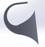
2) Compound horn
Both bent like a spiral or U-shape (see below). Compound horn mouth straight up to first 50cm. MDD is interesting in the bass range as you use multiple resonators. Here author used only two resonators:
Hornlautsprecher
1) MDD with back and front loading
2) Compound horn
Both bent like a spiral or U-shape (see below). Compound horn mouth straight up to first 50cm. MDD is interesting in the bass range as you use multiple resonators. Here author used only two resonators:
Hornlautsprecher
Attachments
I enclose a diagram for realizing the acoustic loads for a 5” driver. When I have time I will try them with the Ciare HX135 driver. I don't have a suitable 3D printer available so I will use 10mm honeycomb polypropylene.
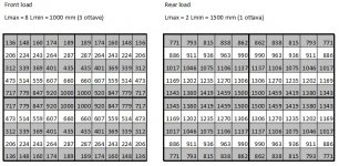
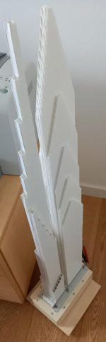
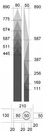
Each acoustic load is a matrix of 10 x 10 guides. Each guide has a section of 10 x 10 mm. The guides are organized in four symmetrical blocks of 25, the highest guides in the center and the lowest on the outside. The scheme can also be reorganized according to aesthetic needs.
The front acoustic load has Lmax = 8 Lmin = 1000 mm, the rear acoustic load has Lmax = 2 Lmin = 1500 mm. Measurements can be changed in scale.
The section of the single waveguide of 10 x 10 mm derives from the availability of alveolar polypropylene of that size. I have verified that 5 mm is few. With a 3D printer you could also do tests with other measures, the best could be 8, 12, 15 or ?? mm (to be checked at the SPL levels you need).
I have never used a compression driver, with the 3D printer a fitting must be made to adapt the driver output to the input of the front MDD acoustic load.
Attachments
MDD3C89
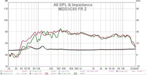
The MDD3A89 and MDD3B89 projects use alveolar polypropylene with reduced thickness. With 5 mm and 2.5 mm the section of each wave guide is less than the length of a half wave so that the diffraction emission has a spherical shape. The reduced sections increase the acoustic impedance with the result that the high frequency emission is attenuated. In the MDD3C89 prototype the front acoustic load is made of 10 mm thick alveolar polypropylene. The medium and high frequency emission increases by a few dB. The frequency response is more balanced and the positioning is less critical for the reproduction of low frequencies. The 10mm honeycomb polypropylene is also stiffer and reduces the problem of spurious waveguide vibrations.
The waveguides of the front acoustic load are made by gluing 5 appropriately shaped 10 mm honeycomb polypropylene panels. In the same panel, 6 wave guides are obtained. The waveguides of the rear acoustic load are made by gluing 10 panels of alveolar polypropylene with a thickness of 5 mm. About 25 waveguides are obtained in the same panel.
In the frequency response there remains a depression between 3 and 4 KHz, probably in relation to the geometry of the waveguides. In the next prototype I will increase the total section of the front load and I will change the geometry of the system, the aim is to recover a few more dB on the mid and high frequencies.
Link:
Claudio Gandolfi - MDD (Multi Delays Diffraction Loudspeaker)
MDD3A89
Attachments
Last edited:
1a-direct
I made the “1a-direct” prototype to measure the attenuation caused by the alveolar polypropylene waveguides and understand the reason for a further reduction of about 5 dB at 3.25 KHz in the MDD3C89 project.
In my opinion it is not an improvement in the audio quality of the previous projects. The scheme (similar to transmission lines) can be used to test MDD technology.
Link:
Claudio Gandolfi - MDD (Multi Delays Diffraction Loudspeaker)
1a_direct
Attachments
MDD3D89
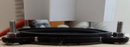
With the 1a-direct project I verified that, without realizing it, I gradually attenuated the high frequency emission project after project. With the MDD3D89 project, the high frequency emission is improved over 5 dB at a minimum between 3 and 4 KHz of the previous MDD3C89 project. I used the same parts of the MDD3C89 project by taking the driver outside and mounting the front acoustic load a few millimeters above it.
Since the speaker is omnidirectional, the same level as in the direct response on axis cannot be reached, the energy of the frontal lobe is distributed at 360 degrees. With the prototype MDD3D89 the difference in the high frequencies is however clearly perceptible.
Due to my habit of listening with MDD systems, I continue to prefer diffraction emission to the direct one of the 1a-direct project. With the prototype 1a-direct the highs are more evident but at certain times they are annoying.
The MDD3D89 project is simple to make and cheap, around 50 euros including the 3FE25 drivers from Faital-Pro. Drivers that continue to surprise me, even after dozens of systems created, for the quality of the reproduction.
Link:
https://www.claudiogandolfi.it/
https://www.claudiogandolfi.it/mdd3a89.html#d
https://www.claudiogandolfi.it/1a_direct.html
Attachments
MDD3G100
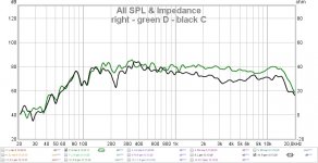
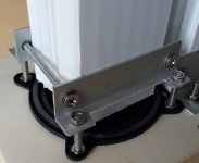
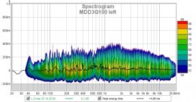
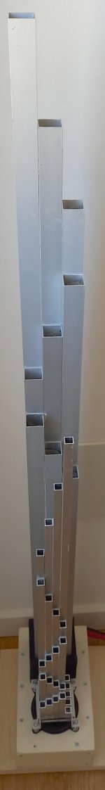
The MDD3G100 project combines the best of the 34c9 and MDD3D89 prototypes, the rigidity of aluminum and the double acoustic load: closed MDDBL and open MDDFL. The increased stiffness reduces spurious vibrations. The double acoustic load distributes high frequencies more effectively at the height of the listener's ears. On listening, the improvement is evident, in the measurements there is a reduction in distortion.
https://www.claudiogandolfi.it/
https://www.claudiogandolfi.it/mdd3a89.html#g
Attachments
MDD3H240
In this period I am doing tests using front MDDFL and rear MDDBL acoustic loads taken from different projects, in some cases the results are excellent.
In tests, the more rigid aluminum is less sensitive to spurious resonances. It is the material that generates less distortion. Its main drawback is the cost, which is why most of the acoustic loads are made of plastic.
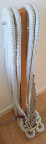
With the rigid PVC, the alveolar propylene and the spiral sheath, acoustic loads up to 2 meters can be easily built with 10 - 20 euros of material. The increase in length extends the frequency response downwards. In empirical tests, 40 Hz are reproduced in the environment with a maximum length of 2 meters.
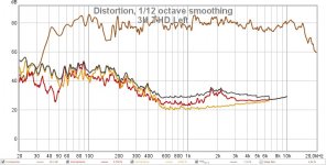
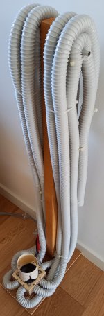
The MDD3H240 project uses the aluminum front loading of the MDD3G100 prototype. The rear acoustic load in spiral sheath is obtained from parts of the 22C71L8 project. There is an increase in distortion below 300 Hz compared to the MDD3G100 prototype, the defect is secondary to the advantage of the extension of the bass response. In the mid and high frequencies the MDD3G100 and MDD3H240 prototypes are similar.
https://www.claudiogandolfi.it/
https://www.claudiogandolfi.it/mdd3a89.html#h
In this period I am doing tests using front MDDFL and rear MDDBL acoustic loads taken from different projects, in some cases the results are excellent.
In tests, the more rigid aluminum is less sensitive to spurious resonances. It is the material that generates less distortion. Its main drawback is the cost, which is why most of the acoustic loads are made of plastic.
With the rigid PVC, the alveolar propylene and the spiral sheath, acoustic loads up to 2 meters can be easily built with 10 - 20 euros of material. The increase in length extends the frequency response downwards. In empirical tests, 40 Hz are reproduced in the environment with a maximum length of 2 meters.
The MDD3H240 project uses the aluminum front loading of the MDD3G100 prototype. The rear acoustic load in spiral sheath is obtained from parts of the 22C71L8 project. There is an increase in distortion below 300 Hz compared to the MDD3G100 prototype, the defect is secondary to the advantage of the extension of the bass response. In the mid and high frequencies the MDD3G100 and MDD3H240 prototypes are similar.
https://www.claudiogandolfi.it/
https://www.claudiogandolfi.it/mdd3a89.html#h
Attachments
Last edited:
MDD3T240 with acoustic transformer
In the MDD3T240 project I use an "acoustic transformer" as front acoustic load, the term indicates the fact that the high pressure sound wave fronts near the cone are transformed into reduced pressure wave fronts on larger surfaces. The acoustic transformer exploits the deformability of the wave guide crossed by the sound waves. Acoustic diffraction does not disappear and operates in synergy with the deformations, generating secondary sound waves, delayed and consistent with the primary emission.
The horn loading does the same thing but is much more complex to build. With just a few cents you can easily build an omnidirectional front acoustic load for mid and high frequencies. For the acoustic transformer I do not have a mathematical model and I recommend its use to those interested in experimenting with non-standard technical solutions. It is a project that I have already used years ago, I suspended it because it was not suitable for the reproduction of low frequencies. I am available to anyone wishing to deepen the subject.
Claudio Gandolfi - MDD (Multi Delays Diffraction Loudspeaker)
MDD3T240
Attachments
"Transformer" is an interesting concept. For sure, ONLY a true horn is the elegant engineering solution for connecting a cone to thin air. But I don't see how that applies here?
What I do see is multiple labyrinths. With a single path, you always get the familiar freq hills and valleys. But these can be nicely controlled with stuffing and they are minor compared to the bigger influence of the room modes.
Another advantage is the separation in distance between the driver and the multiple exit ports that offers spatial diversity. The more mixing and variation the better. But again, even a single very long labyrinth (like mine that exits at the ceiling of my room) provides most of the advantage of spatial dispersion.
Haas effect
The acoustic transformer and the horn have one thing in common, the acoustic pressure of a wave front is distributed over a much larger area than the cone that generates it. The acoustic pressure near the cone is greater than at the outlet. In electrical transformers a high voltage is transformed into a lower one, which is why I used the term acoustic "transformer". End of analogies.
The horns are described by mathematical models developed and validated over tens of years, for my acoustic transformer at the moment there is only empirical evidence.
Another important difference is that the horn is directive while the acoustic transformer intercepts part of the acoustic energy emitted upwards by the driver and deflects it 360 degrees on the horizontal plane.
The acoustic transformer is useful if a driver has a frontal emission on the high frequencies that is too prominent, for my listening habits the direct emission of the Faital-Pro 3FE25 is annoying (1a-direct project). I solved the problem with the omnidirectional MDDFL front loading of the MDD3G100 and MDD3H240 projects. The energy usually concentrated in a frontal lobe is distributed in a much greater volume with a lower sound pressure level. Subsequently I obtained the same result with an acoustic transformer built by folding a sheet of cardboard, project MDD3T240, it is slightly lost in definition, but the quality of the reproduction remains very high.
In the acoustic transformer the emission zones are 3 and all with omnidirectional characteristics.
1 - Between the driver and the waveguide there is a first emission by diffraction of all the frequencies that arrive at the edge of the driver itself.
2 - The side walls of the waveguide are deformed by the pressure of the sound fronts that cross it, other coherent and delayed secondary sound waves are generated. They are caused by an undulation that travels up the surface of the waveguide at the speed of sound in the air. The magnitude of the effect changes with frequency.
3 - The upper edge of the waveguide generates further coherent and delayed secondary waves by acoustic diffraction.
A fraction of the acoustic energy emitted is directed upwards and is subsequently reflected from the ceiling into the listening room.
The variation in the sound pressure level is not enough to explain the perception of improved listening quality. In your system you have spaced the output from the primary emission. In my MDD projects I split the wave front emitted by the driver and multiplied the number of outputs.
Here I repeat my working hypothesis to explain the best listening quality of these cases. In Haas's study of the precedence phenomenon, two identical sounds are perceived as one sound if delayed by a few milliseconds. About 5 milliseconds allow you to distinguish two clicks, about 40 msec allow you to separate more complex sounds.
As in a painting seen through glass, the brain must distinguish the original image from any reflections on the glass itself. A single reflection can be more troublesome than a series of mutually compensating reflected images.
In a small listening environment, sound reflections can be created with delays greater than 5 msec which duplicate the perception of some sounds. A great speaker can generate very realistic reflections that complicate the decoding of sounds. The MDD3T240 project generates by diffraction coherent acoustic signals with delays from 1 to 6 msec. The reflections on the walls generate additional sound fronts with delays of more than 6 msec which eliminate any empty intervals between the beginning and the end of the envelope of a sound.
With MDD technology, the Haas effect cannot be detected. The commitment to decoding sounds decreases and listening pleasure increases.
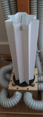
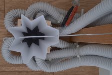
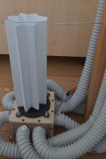
MDD3K240 Front acoustic load with triple Karlson profile
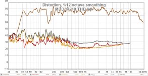
In this MDD3K240 project, the Karlson triple profile front acoustic loading replaces the aluminum MDDFL front acoustic loading of the MDD3H240 prototype. This project is also very cheap and simple to make.
The horizontal omnidirectional emission is generated in three areas.
1 - In the triangles there is a first emission by diffraction of all the frequencies arriving at the edge of the driver itself.
2 - The rectangular slits emit by diffraction in three lobes of approximately 180 degrees partially overlapping to cover the horizontal plane. Other coherent secondary sound waves are generated.
3 - The upper edge of the wave guide generates further coherent and delayed secondary waves of about 0.3 milliseconds by acoustic diffraction.
A fraction of the acoustic energy emitted is directed upwards and is subsequently reflected from the ceiling into the listening room.
Compared to the MDD3T240 prototype, there is the advantage that the front acoustic load has a rigid structure, resists shocks that could deform the acoustic paper transformer and change its characteristics. The frequency response does not depend on the deformation of the wave guide but only on the acoustic diffraction which is controlled by the geometry of the structure.
This is a first prototype to be improved but even with rough profiles it is very pleasant to listen to. It is ideal for omnidirectional economic systems. The shape and size of the profiles are able to influence the frequency response. Before studying the frontal acoustic load better I will try to eliminate the drop in frequency response between 150 and 160.
Claudio Gandolfi - MDD (Multi Delays Diffraction Loudspeaker)
MDD3A89
Attachments

Last edited:
A very nice FR and THD, although not super low yet. Maybe you have found a good rear-wave sequestering that is neither tuned (BR, TL) nor wastes the wave (sealed).
Might look odd is most rooms, but a great possibility is to think of the speaker as a sub and with the pipes spread around the room (or even just across the speaker wall). Might have the benefits of multiple subs that we are all keen to use. But with these flexible pipes, you can have them terminate anywhere on the wall, high and low, that you want. Certainly a perfect a multiple-sub concept.
(They look like vacuum cleaner hoses to me. In a previous house, I built a central vacuum cleaning system and bought many meters of the hoses so as to reach all corners.)
You have well described the operation and potential of the MDDBL rear acoustic load. For each frequency there is a path of suitable length to effectively transfer the sound pressure from the rear compression chamber to the room. There remains the problem of the resonances generated by the room, the responses of the two channels are different.
I have to check if the minimum at 150 Hz is related to the material used for the waveguides. The spiral sheath is produced for external electrical systems, it has a minimum residual elasticity which could be the cause of the irregularity in the frequency response. The fastening of the guide is to be improved, I think that greater rigidity would lead to a reduction in distortion at the lower frequencies.
I have to check if the minimum at 150 Hz is related to the material used for the waveguides. The spiral sheath is produced for external electrical systems, it has a minimum residual elasticity which could be the cause of the irregularity in the frequency response. The fastening of the guide is to be improved, I think that greater rigidity would lead to a reduction in distortion at the lower frequencies.
Attachments
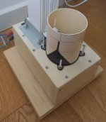
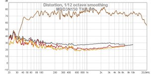
MDD3M150 Front acoustic load in aluminum and rear acoustic load in alveolar polypropy
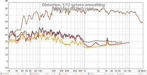
The MDD3M150 prototype is a new combination of acoustic loadings made with the material at my disposal.
The MDDFL front acoustic load in aluminum and the base are the same used in the MDD3G100 prototype.
Change the length of the MDDBL rear acoustic load in alveolar polypropylene. With an Lmax of 1500 mm the frequency response is more extended than the MDD3G100 prototype (Lmax 1000 mm) and reduced compared to the MDD3H240 prototype (2400 mm).
The most interesting measure is the reduced distortion compared to previous prototypes.
https://www.claudiogandolfi.it/
https://www.claudiogandolfi.it/mdd3a89.html#m
Attachments
Member
Joined 2009
Paid Member
Attachments
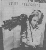
Thanks for this new report of structures similar to my MDD prototypes used for directional microphones. Other posts on the subject have been published in this thread:
https://www.diyaudio.com/forums/pla...nidirectional-single-drive-6.html#post6155092
https://www.diyaudio.com/forums/pla...nidirectional-single-drive-2.html#post5946103
The multiple waveguide structure can be used as an omnidirectional acoustic load on the entire audio band, the driver replaces the microphone directly. The only difference I noticed is the linear distribution of the lengths, in the acoustic loads MDD the distribution is logarithmic.
The single waveguide structure with side openings is not suitable for the reproduction of low frequencies. I think it can work well as a front acoustic load of the latest MDD3K240, MDD3T240, MDD3M150 prototypes. Before using it I still have to figure out how to optimize the size.
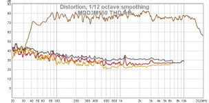
MDD3N150 Triple Karlson profile front acoustic load, MDDBL in alveolar polypropylene
The MDD3N150 prototype uses the same front acoustic load as the MDD3K240 prototype with a triple Karlson profile. The MDDBL rear acoustic load in alveolar polypropylene and the base are the same used in the MDD3M150 prototype.
As in the MDD3M150 prototype the distortion is reduced, it is easier to build.
Attachments
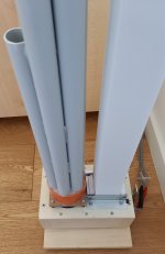
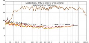
MDD3S150 Front acoustic load in rigid PVC and rear in alveolar polypropylene
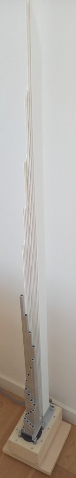
The MDD3S150 prototype uses the same front acoustic load as the MDD3FE25d prototype with seven rigid PVC waveguides. The MDDBL rear acoustic load in alveolar polypropylene and the base are the same used in the MDD3M150 prototype.
The base is very versatile and allows me to try out many combinations with the acoustic loads I have made. Also in this prototype the reproduction is excellent. The greater length from the frontal acoustic load increases the range of delays emitted to almost 5 milliseconds, for me it is an advantage but it could be my subjective preference not shared by others.
Claudio Gandolfi - MDD (Multi Delays Diffraction Loudspeaker)
MDD3A89
Attachments
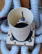
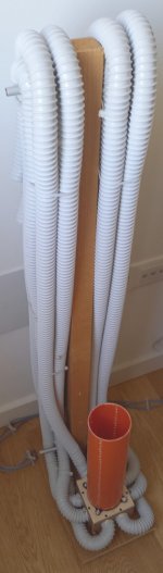
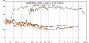
MDD3J240
The MDD3J240 project has the same rear acoustic load as the MDD3H240 and also the same base.
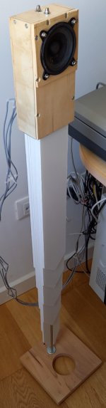
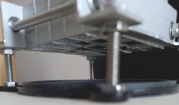
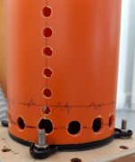
Change the front acoustic load MDD tube , a single waveguide in PVC with a diameter of 80 mm on the outside that fits without modification to the rubber front seal of the Faital-Pro 3FE25 driver. The 9 mm holes at the base create an acoustic short-circuit that makes the system open at both ends of the waveguide. The four series of 5 mm holes generate by diffraction coherent secondary waves with delays from 0 to 1 milliseconds.
The reproduction is excellent even if it can still be improved.
Claudio Gandolfi - MDD (Multi Delays Diffraction Loudspeaker)
MDD3A89
https://www.claudiogandolfi.it/mddfl.html#j
The MDD3J240 project has the same rear acoustic load as the MDD3H240 and also the same base.
Change the front acoustic load MDD tube , a single waveguide in PVC with a diameter of 80 mm on the outside that fits without modification to the rubber front seal of the Faital-Pro 3FE25 driver. The 9 mm holes at the base create an acoustic short-circuit that makes the system open at both ends of the waveguide. The four series of 5 mm holes generate by diffraction coherent secondary waves with delays from 0 to 1 milliseconds.
The reproduction is excellent even if it can still be improved.
Claudio Gandolfi - MDD (Multi Delays Diffraction Loudspeaker)
MDD3A89
https://www.claudiogandolfi.it/mddfl.html#j
Attachments
- Home
- Loudspeakers
- Planars & Exotics
- MDD Multi Delays Diffraction (Multi TL, omnidirectional, single drive, ...)