Looked for Teflon (PTFE) in the Rogers catalogue.It is a Rogers material. It was expensive and hard to get then. Same with the dustcover film. Probably easier today. But still expensive.
Nothing there.
Can you please help me out here. What is the material type.
IMHO a Teflon plate can't be 0.025" thick and be rigid.
Searching for the wrong term in the Rogers catalogue. Should have looked for PTFE instead of Teflon.
The dielectric material for the original 22 pF plate capacitor in the Quad 63 and newer delay line is 1.5 mm thick unknown material.
The copper surface is 34 x 19 mm = 646 square mm
For imperial sizes.
Thickness is 0.06 inch and surface is 1 square inch
This results in a dielectric constant value of the original material used of around 5.5
Normal dielectric constant for most PCB materials is between 3.5 and 5.5 (depending of frequency). So most likely the original material used by Quad is some kind of old PCB material. Probably custom made for the Quad ESL-63.
Roger PTFE variants:
Rogers ro3000 series has 3 variants Dk 3.0, 3.5 and 6.15
Rogers RT series comes in may varieties Dk from 2.0 to 10.0
Rogers TMM series are 3.3 to 12.85
Note: All PCB material is enforced, so not PURE PTFE material but glass fiber or ceramic re-enforced.
So most likely, with the thickness 1audio provided (0.025 inch), Rogers RT series 5870/5880 material was used for the Crosby mod.
https://rogerscorp.com/-/media/proj...a-sheets/rt-duroid-5870---5880-data-sheet.pdf
Picture of the original plate capacitor as used in very early ESL-63
Amazon Photos
Last edited:
I have mentioned this many times and also Sheldon.
The internal wiring on the HV side has extremely high impedance and stray capacitance plays a significant role here.
IF... I say IF for any reason someone wants to "improve" the sound, the wire shall be as thin as possible to reduce the capacitance.
If the wire resistance goes up to 1kohm each, it would not change the output level at all. In fact adding a 10kohm (10 000 ohm) resistor to each delay ring could be beneficial. The explenation for that is that each dealy ring is a capacitance (driven by an inductance with high resistance already) in parallel with the diagonal compensating capacitors, there is no electric damping between those capacitances that causes ringing. The transmission line termination 300k and 4x330pF is there to secure that the voltage ringing never exceeds the voltage from the transformer.
The 10k resistor would not effect output at all but will introduce damping.
2/3 of the current out from the secondary winding is lost in all the capacitors. Only 1/ of the current is fed to the stators.
The 4x330pF capacitors can be experimented with... i have tweaked around A LOT!! During the years finding ways to "improve" the construction.
For 4 panels operation the gain is less significant compared to 6 or 8 panel operation (yes 8 panels sounds great!).
After Peter Walker the 6 panels was introduced. NOTHING in the delay line circuit was changed. Thats really bad. Because the benefit of fiddling and optimize the circuit is quite big. Not subtle, big. Adding a double set of transformers (if you have spares) and let them feed your 6 bass panels, via an active crossover/amplifier, and feed the center segments with 100-20kHz only give you 10dB more in dynamic (higher output before breakdown) Remember that the dealy line gets ALL the low frequency and that the center segments is forced to play fullrange.
Thats the reason why an active filter lifts the QUADs to a complete different level. The drawback is that it is hard to get a dynamic woofers to integrate with all electrostats. By rebuilding your speakers as described you will get both worlds.
I guess I have to make a separate thread about this soon... and publish some of the measurements and pictures.
10dB increased output volume before center rings sections touch the stators. That's the absolute limit since the membrane has a hard time to travel any further than this. Measurement with some popmusic confirms this. Probably arcing for me since i have ripped out all protection circuits... but for rest of you "chickens" ") your protection circuit will produce even more distortion than normal, yes.
your protection circuit will produce even more distortion than normal, yes.
But you have a valid point, it should be mentioned that if you play music with little information below 100Hz its not a good idea.
If you are listening to Infected mushrooms, the gain is probably close to 15dB ... just do a spectrum analysis and eyeball.
your protection circuit will produce even more distortion than normal, yes.But you have a valid point, it should be mentioned that if you play music with little information below 100Hz its not a good idea.
If you are listening to Infected mushrooms, the gain is probably close to 15dB ... just do a spectrum analysis and eyeball.
I can make it easier to understand the 10 dB increase in max output. The transducer is capacitive and its output actually increases by about 10 dB/decade when looking at the voltage on the stators. With a common voltage on all the panels the breakdown comes from the lowest frequency (has the highest voltage for a given output). Move the LF limit from 20 Hz to 150 Hz moves the output up proportionally. I have long promoted crossovers in the 100 Hz range. On most music (not Hip Hop) the energy is distributed equally on both sides of 100 Hz making it a good dividing point. The quad panels have a self resonance somewhere below 100 Hz and avoiding that region with an external sub can work well.
I would like to explore the 10K resistor some more. Have you tried it in Han's simulation? I want to better understand how it helps and what it does.
I would like to explore the 10K resistor some more. Have you tried it in Han's simulation? I want to better understand how it helps and what it does.
I have not done simulations. 10kHz will cause a crossover with 22pF at 800kHz. So we do not have to worry about some loss of treble! The theory behind it is from Baxandalls description of the ESL63. Since the delay line consist of a lattice of inductors capacitors (also the electrostatic panel is a capacitor) there can be cases when the voltage actually increases compared to output voltage from the secondary. The inductors has quite high resistance in itself so damping in those is sufficient, but the capacitor-capacitor lattice between stator and capacitors has no damping but by introducing 10k in series with both each stator ring and 22pF lattice capacitors (the diagonal ones) we ensure that resonances will be dampen.
The 22pF capacitors is discussed when it comes to linearity! Teflon is nice and the DIY teflon caps is just great! Maybe on the costly side.
The hysteresis from dielectric absorption (nonlinearity) in a capacitor was linearized by a series resistor in an article, and i can not find it... can someone find this?
To make 22 pF plate capacitors of the right size and value, pure PTFE will be too thin to be stiff enough to use. You can only use 0,5 mm thickness to be able to fit the base of the Quad ESL-63 delay line PCB.
The DIY plate capacitors that are often referred to, are made from ceramic enforced Rogers PCB material. That is NOT pure PTFE!
A set of these hand made capacitor were also available as an "upgrade" for some years. Some DIY use glass.
See this thread
The DIY plate capacitors that are often referred to, are made from ceramic enforced Rogers PCB material. That is NOT pure PTFE!
A set of these hand made capacitor were also available as an "upgrade" for some years. Some DIY use glass.
See this thread
This is what I would use today: https://rogerscorp.com/-/media/proj...a-sheets/rt-duroid-5870---5880-data-sheet.pdf It seems really good.
It can be had as a laminate with copper. (that's what they mean by laminate). Its a composite of a very high grade short glass fibers and PTFE Teflon, both materials that behave well for capacitive properties. It has the best performance of any material up to millimeter wave (80 GHZ I think). I may have a sample around here. If I can find it I'll test it on the CLT-1 for linearity. I suspect it will be essentially distortion free to 1 KV (the limit of the system).
I have replaced most of the electronics in my 2905's to good effect. SUT's replaced by Plitron toroids (V gain 75 instead of 250) - big improvement, no mistake. Built solid-state push pull Class A amps to have +/-25V rails so that the diaphragms could see no more than 3800V swing - so no need for speaker protection and out it went. Much improved sonics. Added to the Plitron SUT, could use nichrome resistance wire to tune the SUT and substitute for the factory tuning circuit. So no signal shaping. Much improved.
Replaced delay line ceramic caps (these have HUGE dielectric coefficient) with Rogers PTFE (good) and with air gap (better). Replaced HV supply with the Reference from Electrostatic Solutions, much improved. Just about to try improving the 10M resistor and .047 cap. Who knows?
But after all this, the factory 2905 used for HT centre channel sounds damned good too. Quite different, not as clean, not as pure, but very easy to listen to. Notably better for a digital input. YMMV
No measurements, sorry. The difference between PTFE and air gap are only significant to ESL nerds, I suspect - the PTFE are still a touch harsh. Anyway the PTFE are a pig to make and the air gaps can be bought as variable caps from Nebraska Surplus, or made up from copper discs. I compulsively plated my discs with silver, but I think that might have been silly.
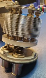
This is a copper air gap capacitor that I made for another purpose, but it shows the principles. Pretty obvious, ain't it?
The discs are 2.75" in diameter, assembled on five pillars. The central pillar is for mounting. The two white nylon pillars are for stability. The two metal pillars are for stability and serve as the terminals. Separation is done with small thin washers of preferably PTFE, or nylon, threaded onto the pillars.
This is a low voltage piece measuring 700pF, for another purpose. For the Quads, smaller discs and more air gap is used for 22pF and 10pF at 5kV.
looks a lot like one of these: https://www.ietlabs.com/genrad-1403-series-high-frequency-standard-capacitor.html Works well but a lot of effort to make and not small.
Attachments
WRT obsession the GR caps punch large holes so the alternate plates do not need insulating washers. Here is a thread on troubleshooting them https://www.eevblog.com/forum/metro...f-capacitor-adjustment/msg3571971/#msg3571971 The really exotic variations are filled with nitrogen.
In this application rounding over each sharp edge on the plates is critical to prevent corona discharge. The spacing is also an issue- I think you need like 3mm between plates to get more than 3 KV breakdown.
You might not want to silver plate the plates https://nepp.nasa.gov/whisker/other_whisker/silver/index.htm
- Home
- Loudspeakers
- Planars & Exotics
- QUAD 2805/2905 dismantling: in pictures (part 2)