FEMM
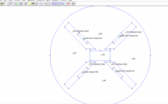
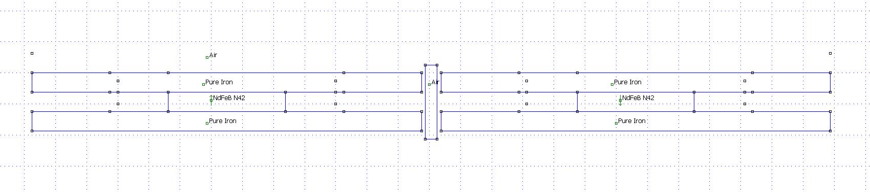
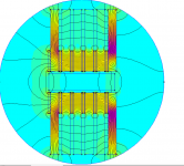
I tried to see if I could simulate the way I have my magnets in between the steel plates but the software seems that doesn`t like it.
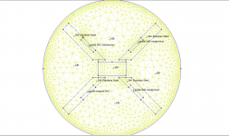
It comes with an error for the mesh which says that I didn`t define all the block which I definitely did as shown in the picture.
Now I think that the problem is that I tried to draw the magnets as they are under the metal plates. Any suggestions?
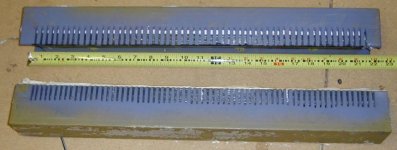
metal plates 75mm long x 13mmwide
magnets 25mm long 5mm wide grade 42 neodymium magnet (4.3kg pull)
I tried to see if I could simulate the way I have my magnets in between the steel plates but the software seems that doesn`t like it.
It comes with an error for the mesh which says that I didn`t define all the block which I definitely did as shown in the picture.
Now I think that the problem is that I tried to draw the magnets as they are under the metal plates. Any suggestions?
metal plates 75mm long x 13mmwide
magnets 25mm long 5mm wide grade 42 neodymium magnet (4.3kg pull)
Attachments
Last edited:
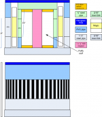
AMT layout in Archicad
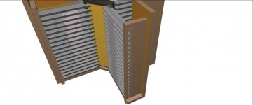
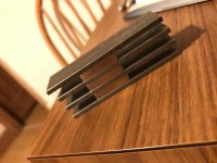
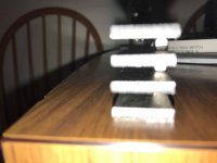
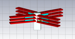
Here are some pictures with the layout structure of my design of AMT which I still could not simulate it to see if the 25x5x5mm N42 magnets in between the steel plates will be enough to ensure an even magnetic field for a diaphragm of around 140mm high and 40mm wide.
Of course, is missing the fake bottom where I`ll put the hardware for the digital filters and also the top part.
All the parts will be laser cut and the walls where I`ll insert the magnets and steel plates is made of clear acrylic and I plan to use some silicon-based adhesive to ensure are no vibrations.
What do you think?
Attachments


I tried to see if I could simulate the way I have my magnets in between the steel plates but the software seems that doesn`t like it.
It comes with an error for the mesh which says that I didn`t define all the block which I definitely did as shown in the picture.
Now I think that the problem is that I tried to draw the magnets as they are under the metal plates. Any suggestions?
metal plates 75mm long x 13mmwide
magnets 25mm long 5mm wide grade 42 neodymium magnet (4.3kg pull)
You have three AIRs too many. Only one is needed.
You cannot simulate with the magnets in between the steel plates, FEM is no three dimensional.
Here are some pictures with the layout structure of my design of AMT which I still could not simulate it to see if the 25x5x5mm N42 magnets in between the steel plates will be enough to ensure an even magnetic field for a diaphragm of around 140mm high and 40mm wide.
Of course, is missing the fake bottom where I`ll put the hardware for the digital filters and also the top part.
All the parts will be laser cut and the walls where I`ll insert the magnets and steel plates is made of clear acrylic and I plan to use some silicon-based adhesive to ensure are no vibrations.
What do you think?
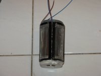
Are the magnets magnetized through the largest surface, that is the surface attached to the steel plates?
Where do you think the magnetic flux will be?
Are the magnets magnetized through the largest surface, that is the surface attached to the steel plates?
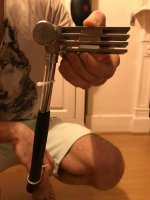
I think yes, I made some pictures with the magnets and plates and also with a hammer which is held by the flux made at the end of the steel plates.
Where do you think the magnetic flux will be?[/QUOTE]
On the website, it says Magnetic Face: 25 x 5mm so i assume you`re right they are magnetised largest surface
here is also a link with the magnets i have 25 x 5 x 5mm thick N42 Neodymium Magnet - 3.4kg Pull | first4magnets.com
I think is around the length and also directed by the plates towards the center of the membrane.
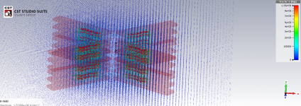
I made the structure in CST EM studio which is a 3D simulator but I`m still waiting for a teacher from university to show me how to get a simulation successfully.
I think yes, I made some pictures with the magnets and plates and also with a hammer which is held by the flux made at the end of the steel plates.
Where do you think the magnetic flux will be?[/QUOTE]
On the website, it says Magnetic Face: 25 x 5mm so i assume you`re right they are magnetised largest surface
here is also a link with the magnets i have 25 x 5 x 5mm thick N42 Neodymium Magnet - 3.4kg Pull | first4magnets.com
I think is around the length and also directed by the plates towards the center of the membrane.
I made the structure in CST EM studio which is a 3D simulator but I`m still waiting for a teacher from university to show me how to get a simulation successfully.
Attachments
Last edited:
Are the magnets magnetized through the largest surface, that is the surface attached to the steel plates?
I think yes, I made some pictures with the magnets and plates and also with a hammer which is held by the flux made at the end of the steel plates.
Where do you think the magnetic flux will be?
On the website, it says Magnetic Face: 25 x 5mm so i assume you`re right they are magnetised largest surface
here is also a link with the magnets i have 25 x 5 x 5mm thick N42 Neodymium Magnet - 3.4kg Pull | first4magnets.com
I think is around the length and also directed by the plates towards the center of the membrane.
I made the structure in CST EM studio which is a 3D simulator but I`m still waiting for a teacher from university to show me how to get a simulation successfully.
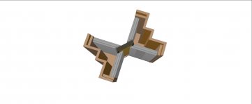
Ok, so this might be another view of it?
Ok, so this might be another view of it?
the 4 walls where the structure sits have an angle but I tried the way you show above and it doesn`t look good at all.
I might have to add or change the location of the magnets closer to the membrane or even to change the whole design if I can`t get enough flux
I`ll try different angles more appropriate with my design to see if gets any better...
Attachments
Ok, so this might be another view of it?
the 4 walls where the structure sits have an angle but I tried the way you show above and it doesn`t look good at all.
I might have to add or change the location of the magnets closer to the membrane or even to change the whole design if I can`t get enough flux
I`ll try different angles more appropriate with my design to see if gets any better...
So if that's how you want your magnets, it will not work.
Try to understand how it works in in post #16 above.
Last edited:
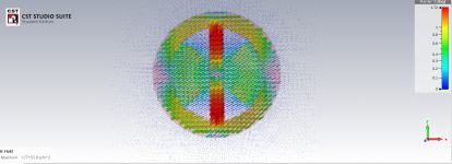
3d simulation
I tried to simulate 3D but I have a problem because the magnet doesn`t interact with the iron in the simulation, thus it doesn`t guide the flux towards the membrane.
I`m still trying with this design since I done the whole envelope and measurements.
I was thinking to place the magnets with the long face towards the membrane if that was the problem but I don`t know yet.
Also, the design made in post 16 uses a huge block of ceramic magnets which i don`t have. I already spend most of my project budget on the Neodymium magnets.
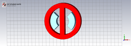
I also did a simulation on a magnet surrounded by iron to show how in a correct simulation the Iron interacts with the magnets and guide the flux.
I`ll update the thread once I figure out how I`ll fix this problem
I tried to simulate 3D but I have a problem because the magnet doesn`t interact with the iron in the simulation, thus it doesn`t guide the flux towards the membrane.
I`m still trying with this design since I done the whole envelope and measurements.
I was thinking to place the magnets with the long face towards the membrane if that was the problem but I don`t know yet.
Also, the design made in post 16 uses a huge block of ceramic magnets which i don`t have. I already spend most of my project budget on the Neodymium magnets.
I also did a simulation on a magnet surrounded by iron to show how in a correct simulation the Iron interacts with the magnets and guide the flux.
I`ll update the thread once I figure out how I`ll fix this problem
Attachments
george995, stainless steel is not magnetic.[/QUOTE
]
I use mild steel which is not coated with anything
It was in the 1980 issue of the Audio Amateur Loudspeaker Projects
Published by: Audio Amateur, Incorporated, USA 1980
ISBN 10: 0833801937 / ISBN 13: 9780833801937
I was gonna build one but never did.
I actually made all made most of the parts and was working on construction methods for the Diaphragm and got a huge stack of magnets that ended up in a build for a straight ribbon driver.
But then again I was more in to the the Roger Sanders ESL projects at the time that are in it as well.
jer")
https://www.americanradiohistory.com/Archive-Amateur-Audio/Audio-Amateur-1977-2.pdf. (see page 15 in the magazine)
I've got a hardcopy of that. I also have the original typewritten version
.That article was written after I graduated with a degree in philosophy and I didn't know what was next in my life (ended up going back to school to get an engineering degree). I probably made 20 to 30 Heil variants around that time.
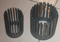
If you are interested in resurrecting the Heil, you should consider a circular version using commercially made diaphragms. The magnet design is fairly simple, and the design is omnidirectional in the horizontal plane. The circular structure is described in the original patents by Heil, but to my knowledge nobody pursued that design. The magnet structure is fairly easy to DIY using standard sizes of iron pipe.
Attachments
Thanks. Hard to believe that was over 40 years ago.
There was an update to the article in issue 1979-4 that described how to etch the diaphragm. See the letter on page 40:https://www.americanradiohistory.com/Archive-Amateur-Audio/Audio-Amateur-1979-4.pdf. I made quite a few of those diaphragms, but I doubt that I would have the required patience anymore. The most difficult diaphragm was for some drivers that were about 22" inches tall--see the picture.
Again, I would encourage anyone interested in the AMT design to try the circular version. I started a small one that used the diaphragms from the Hygeia RT2002 and a larger one that used 4 diaphragms from the Aurum Cantus AST2560. However, I never finished these prototypes, and the parts are still in a box downstairs. I think there is a lot of promise in that approach, but I just don't have the time or patience anymore to see it through.
Attachments
- Status
- This old topic is closed. If you want to reopen this topic, contact a moderator using the "Report Post" button.
- Home
- Loudspeakers
- Planars & Exotics
- Air motion transformer (replica of the great ESS Heil AMT)