Mats31, This is very useful information. Especially your remarks regarding the use of bees wax to cover the HV points. In the mean time I ordered panasonic smoothing caps and nichicon bipolars. Stokessd informed me that usually he bypassed the bipolar with a 8.2uf polyprop.
There is a contradiction with the (2805)2905 schematic. The 220u bipolar on the actual board is 50v rated whereas the offical schematic is indicating a 250v part.
To be honest I’m not impressed by what seems official technical documentation of these esl’s as available on the net.
There is a contradiction with the (2805)2905 schematic. The 220u bipolar on the actual board is 50v rated whereas the offical schematic is indicating a 250v part.
To be honest I’m not impressed by what seems official technical documentation of these esl’s as available on the net.
The documentation is effectively non-existent on the net, and the 2905 manual that is floating around has a couple of errors on the schematic as well. If the quality of the official documentation bothers you, you should check out the quality of the fasteners and hardware in the speaker itself.
I use 100v 220uF caps to replace the originals when necessary. I also just bypass that cap with a 8.2uF polyprop cap. it all fits without heroic measures.
If you have a 988 or newer, you can fit coke can polyprop caps under the plinth. These are what I've used in the past, although honestly, I don't think it's worth it vs. just using the 8.2uF bypass:
Solen 200uF 400V Polypropylene Capacitor
Sheldon
quadesl.com
What about the polyfuse used in the later Quads like the 2805? It is in series with the capacitor...likely there to help avoid amplifier damage when the SCR clamp activates, but the earlier iterations did not have it. I wonder about the sonic impacts. Have you experimented with bypassing it?…These are what I've used in the past, although honestly, I don't think it's worth it vs. just using the 8.2uF bypass.
In post 13 member bolserst advised me to take measurements of DCV and ACV across the 1000uF cap in the power supply of my ESL. The results in post 15 seemed to indicate that this cap was bad.
Today I replaced the supposedly bad 1000uF capacitor in my 2805 by a fresh Panasonic FR series cap. Of course I was curious enough to take the same measurements again. I was measuring with two meters an analog and a digital one.
Analog VDC 15V
Analog VAC 30V (stable reading)
Digital VDC 15.5V
Digital VAC the same rythmic repeating pattern 38,15,6,2,0 V
And now I am completely flabbergasted. Does anyone has a clue ????
Right now I don't know if the distortion in the esl is still there. I couldn't audition it properly because the ESL is on my workbench. Tomorrow is the proof of the pudding.
In post 13 member bolserst advised me to take measurements of DCV and ACV across the 1000uF cap in the power supply of my ESL. The results in post 15 seemed to indicate that this cap was bad.
Today I replaced the supposedly bad 1000uF capacitor in my 2805 by a fresh Panasonic FR series cap. Of course I was curious enough to take the same measurements again. I was measuring with two meters an analog and a digital one.
Analog VDC 15V
Analog VAC 30V (stable reading)
Digital VDC 15.5V
Digital VAC the same rythmic repeating pattern 38,15,6,2,0 V
And now I am completely flabbergasted. Does anyone has a clue ????
Right now I don't know if the distortion in the esl is still there. I couldn't audition it properly because the ESL is on my workbench. Tomorrow is the proof of the pudding.
The AC voltage shouldn't be that high. It should be a few hundred mV. Does your meter auto-range and you are on the mV scale? Are you measuring right across the cap or from some other reference point?
Sheldon
What about the polyfuse used in the later Quads like the 2805? It is in series with the capacitor...likely there to help avoid amplifier damage when the SCR clamp activates, but the earlier iterations did not have it. I wonder about the sonic impacts. Have you experimented with bypassing it?
I haven't done a lot of tested of its effects, I consider it a safety device and wouldn't defeat it in speakers that I repair for others. For my use, I might bypass it though. When not triggered it has a quite low resistance and effectively not doing a whole lot in the circuit. There's a lot in the speaker that could mess with the sound as much or more than the polyfuse, like the diode bridge and zeners that you are playing in parallel with the panels. And the big series electrolytic cap that we mentioned earlier.
Sheldon
what make/model of voltmeter are you using? stokessd has a good point...if it is auto-ranging, you might be seeing 38mVAC instead of 38VAC which means the power supply is fine. Some meters have buttons to over-ride the auto-ranging and manually cycle thru ranges. If you are indeed seeing 38VAC and 15VDC with the new capacitor, as unlikely as it sounds, the bridge rectifier D14 may be faulty.
Last edited:
re: odd VAC meter readings - it could also be that like many cheap DVMs, clog's does not read AC volts cleanly in the presence of DC offset.
- ie VAC riding on top of the 16v or so DC on this supply.
Try coupling one lead to the meter through a 0.1 - 1uF capacitor when trying to read Vac and see what the meter shows once it settles in 5-10seconds (NB no need for large capacitor value: the meter input impedance will be tens of megaohms, or more; so there will be a slow settling time while the cap charges to the full DC if you use a larger-value cap)
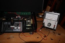
I also have doubts about the results of the measurements. After the latest posts here I couldn't get it out of my mind. Now I have this old Leader AC millivoltmeter. I connected unshielded leads and redid the measuring. As you can see the outcome lies between 60 and 70 mVAC. I am inclined to think this is correct a outcome because it's much more logical (and it suits me much better ") ) Agree???
) Agree???
But the proof of the pudding is the auditioning. I hope I will find some time tomorrow to hook them up to my stereo. Thanks again for all your help.
) Agree???But the proof of the pudding is the auditioning. I hope I will find some time tomorrow to hook them up to my stereo. Thanks again for all your help.
Attachments
First it was mats31 who suggested based on his own experience that a bad smoothing cap in my power supply could be the root cause of the distortion in one my esl's. This opinion was supported by stokessd and bolserst. Confirmed by as it turns out my incorrect measurements.
In hindsight for the wrong reason but I replaced the 1000uF cap. Sometimes you need some luck in life because now my esl's sound as new, clear and clean.
The expertise of you guys was invaluable to me. And I am so happy.
In hindsight for the wrong reason but I replaced the 1000uF cap. Sometimes you need some luck in life because now my esl's sound as new, clear and clean.
The expertise of you guys was invaluable to me. And I am so happy.
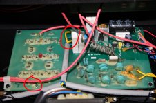
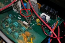
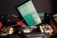
To help other newbs like me I took some pictures. To get easy access to the underside of the board I desoldered 6 wires, one wire left in front of the board, 4 wires left at the back and one wire right in the middle (red circles in the pictures). After undoing 4 phillips screws you can flip the board about 90 degrees. Removing solder with a wick didn't work out well. Later I learned that with lead free solder it's better to apply some leaded solder first.
Three quarter of the board is covered with bees wax (picture). When the job was done I poured some molten wax over the fresh solder. And in several unwanted places.
Three quarter of the board is covered with bees wax (picture). When the job was done I poured some molten wax over the fresh solder. And in several unwanted places.
Attachments
- Status
- This old topic is closed. If you want to reopen this topic, contact a moderator using the "Report Post" button.
- Home
- Loudspeakers
- Planars & Exotics
- Quad 2805 power supply malfunction?