Hello my name is edwin olthuis.
I live in the netherlands. I have succesfully restored a few audiostatics. And right now i got my hands on a pair ofaudiostatics es200 rs elektrostats.
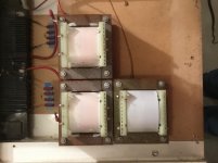
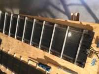
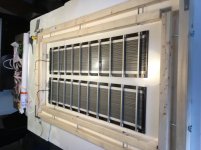
They definately need new foils. But i also noticed that the laminations of the step up transformers are rusted.
My question is. Can the step up transformers be rescued? Or do i have to replace the metal laminations. Or do i have to consider a completely new set of transformers which is difficult to find. I willpost some pictures tommorow.
Regards edwin from holland
I live in the netherlands. I have succesfully restored a few audiostatics. And right now i got my hands on a pair ofaudiostatics es200 rs elektrostats.
They definately need new foils. But i also noticed that the laminations of the step up transformers are rusted.
My question is. Can the step up transformers be rescued? Or do i have to replace the metal laminations. Or do i have to consider a completely new set of transformers which is difficult to find. I willpost some pictures tommorow.
Regards edwin from holland
Hey, that´s *nothing* !!!!
IF you wish, for peace of mind, get an Artist´s brush and paint visible metal, rusty or not, with "oxide converter/stabilizer" paint, simply to stop it rusting to death some 500 years from now (sinc it took about 50 years to reach the current point).")
IF you wish, for peace of mind, get an Artist´s brush and paint visible metal, rusty or not, with "oxide converter/stabilizer" paint, simply to stop it rusting to death some 500 years from now (sinc it took about 50 years to reach the current point).
Hammerite (I always use this for transformers) https://www.hammerite.nl/producten/metaallak-direct-roest-structuur/
With all do respect. If you know how to deal with chemicals then you may use diluted household drain cleaner with muriatic acid. Fortunately enough acid eats rust much faster than iron. Rinse with water, then neutralize with baking soda rinse again and dry. Always pour acid product into water! Do not use stronger than 15% HCl. Reaction does generate hydrogen and may make solution airborne due to bubbling. So face shield and nitrile gloves will do. Piece by piece. It's time consuming but you will be pleased with the results. Drain clean does have inhibitors preventing bare metal damage.
Last edited:
I wouldn't use acid simply because I'd be wary of capillary action drawing it between the laminations.
I'd mechanically clean then paint.
+1 to that.
Only use acid-based cleaning processes if you plan to disassemble the laminations completely. In the assembled state, capillary action will suck the acidic stuff right into the small gaps between the laminations, causing corrosion within the whole stack, shortening the lifetime significantly.
Rundmaus
I think its a little to risky to use acidic chemicals to clean the laminations. But i think i will stick with the mechanically cleaning and painting of the laminations.
But if someone has the schematics of the es200 speaker, that would be great. Otherwise i will figur it out myselfe and post the schematic here on diyaudio.
I will have to desolder the print of the transformers so i can chance the condensators for new ones. And some other stuff has to be renewed. And i will make pictures of the prints for referencing.
NO PLEASE !!!!
Muriatic acid must not be in the same room as Electronics equipment, even less *applied* to it.
You GUARANTEE rapid rusting, corrosion and destruction.
Leave Muriatic acid to tin bucket makers, coffin makers, etc.
A little rust will not hurt transformers, clorhydric/muriatic acid vapours corrode averything within reach.
There is peculiar problem with rust, it occupies more volume than iron.
If you are not afraid I said.
Every freaking chromium coated knob and every piece of aluminium amplifier case and/or hetsink was soaked in acid for quite a time.
Adios, amigos.
P.S. If you do not know how to, please do not look for excuses.
P.P.S. H2SO4 is really hard to get rid of - it's not volatile, while HCl is a gas, soluble in water.
More pictures from the guts of an es200
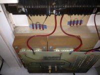
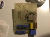
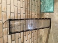
Hello, today i dissasembled the electronics of one audiostatic es200. Here are some pictures.
The schematic starts with a 68 microfarad elco and a resistor of 3.3 ohms. This resistor isnt burned so the previous owner didnt play to loud.
For now i have to follow the traces and make a schematic
Gr edwin
Attachments
Thanks for posting the pictures.
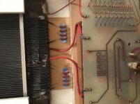
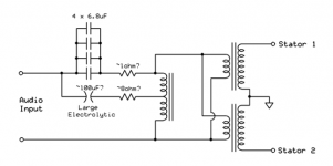
I can help out with the schematic if you post a picture showing the complete back of the printed circuit board. The first image was close, but missing the portion where most of the crossover parts are located. It would be nice to put together the schematic for your 200RS which looks like it has the 3 position switches for adjusting bass and treble like the 300RS.
Attached also is a schematic I started for a ES-300 that somebody had posted board pictures for. I still need to get confirmation on the resistor and capacitor values though.
Pics posted here: Do different components in the filter of an ESL actually effect the sound?
Attachments
Es200 schematic
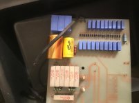
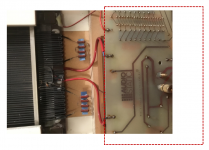
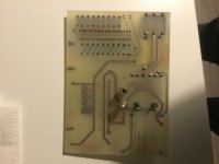
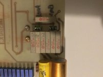
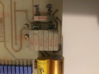
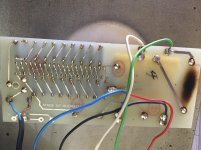
Thank you bolserts for your help. Here are pictures from the boards. Front and back. But what i cant figure out. There is one solderpoint on the bottum left corner of the board that doesnt seem to have a connection with any other point. It is a transformer connection from the mirrordrive transformer on the bottum.
The hights have four 6.8 condensators in parallel
And see the pictures for the resistor values
Perhaps you knowits purpose?
Greetings edwin
Attachments
Last edited:
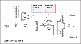
Thanks for the pics! Schematic attached.
The unconnected terminal of the mirror-drive transformer is just an unused tap.
I’m not sure if it was to allow use of one mirror-drive transformer with multiple models that required different ratios, or if it had at one time been used in a configuration where the tap was selected with a switch to change the bass boost amount. All circuits I have seen only used 3 connects to the mirror-drive transformer.
Attachments
Thanks for the schematic. This is going to be a nice journey and project!
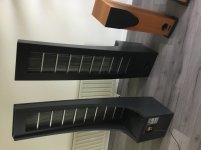
I have also succesfully finished two esh 50 audiostatics. One pair is fully assembled an for one pair i only finished the panels. And i noticed that the dimensions from an esh50 panel is the same as of an es200 panel. But if you really look closer.
The ds spacing is a little bigger. So no fast journey. And no fast panel swapping.
But that should have been obvious because of the mirrordrive and the need of more mylar movement.
I have also succesfully finished two esh 50 audiostatics. One pair is fully assembled an for one pair i only finished the panels. And i noticed that the dimensions from an esh50 panel is the same as of an es200 panel. But if you really look closer
. The ds spacing is a little bigger. So no fast journey. And no fast panel swapping.
But that should have been obvious because of the mirrordrive and the need of more mylar movement.
Attachments
-
 1B0E8966-4E0D-4A4B-90CB-355B2BBADD80.jpg721.9 KB · Views: 67
 -
 47E4F70B-55E4-46E4-8689-902470449F7E.jpg688.6 KB · Views: 50
 -
 A359EC9B-D298-415E-8C75-CA48BE8D0391.jpg541.4 KB · Views: 50
 -
 3DEAD0FC-25B0-4952-BBCE-6083D3040854.jpg477.6 KB · Views: 54
 -
 95B87FCD-B99F-4F32-9E5F-EB3D48EFF28C.jpg765.9 KB · Views: 57
- Status
- This old topic is closed. If you want to reopen this topic, contact a moderator using the "Report Post" button.
- Home
- Loudspeakers
- Planars & Exotics
- Rusty transformer metallaminations