Hmm, interesting.
I'm going to throw an idea out there and I want some feedback on whether it's a bad one.
Tweeter- Aurum Cantus AST25120 Aero Striction Tweeter
Aurum Cantus AST25120 Aero Striction Tweeter 8 Ohm
Woofer- Bohlender Graebener Neo10 Planar Transducer or M165NQ
Bohlender Graebener Neo10 Planar Transducer!
M165NQ/16 Woofer
Subwoofer- BMS 18N862
Speaker BMS 18N862, 8 ohm, 18 inch
Or, would I benefit more from doing something like Few did and just make a big desktop planar?
Last edited:
Im confused..
Isn't this project about Close ( within 20-25 inches) listening at a desk in front of a computer?
with enough work you can likely make those drivers work well, but they will likjley never be as "perfect" than a single driver planer or planer/ ribbon at close distance, And if you want to go very low in a sub at close distance then I assume you dont want a box the size of a refrigerator.
I had a 10 inch sub I added mass to once in a 1 cu foot box that easily did 15 HZ at close distance
It was mercilessly low sensitivity BUT it was real sounding and conveyed hall ambiance to die for.
The point is this IF you can trow away sensitivity and directinal issues ( wich you can at close distance) then the problem of trully great sound is MUCH easyer. If you going to do close and you dont need 120 db then it can be a much easyer job IF wise choices are made
Last edited:
The various options you're weighing seem a bit "all over the map." That compels me to emphasize how different your design and construction process will be, depending on which path you follow. Apologies in advance if I'm misreading, but I want to be sure you have a realistic image of what each sort of project entails. My planar magnetics involved individually gluing each magnet in place, designing the aluminum trace pattern to optimize sensitivity and impedance, figuring out how to cut the pattern reliably, transferring it to a suitable diaphragm.... I went that route because it's the sort of thing that floats my boat. I enjoy the from-scratch aspect.
Buying suitably matched drivers, installing them in a properly designed and constructed enclosure, and working out the crossovers, is a very different endeavor. I don't mean to make any value judgements; I'm just saying the process is quite different and requires a different set of tools and skills.
Whichever way you go, don't fall into the trap of searching for "the best drivers" (there are no drivers that are best for all applications) and losing sight of the real heart of the matter: properly implementing and integrating them into something that doesn't sound like a collection of parts. If you go the from-scratch route, you should include a significant learning curve into your vision of ending up with speakers on your desk. You'll likely throw away many false starts before you end up with a matched pair of drivers that do what you want.
It's all fun, so I don't mean to discourage you. It's just hard to tell from your posts whether you have a realistic view of what each of your choices might entail. Being clear-eyed about the whole process, start to finish, will help you choose the path that best suits your goals, skills, tools, and of course, available time. If you've already designed and built a dozen pairs of speakers then ignore all this; you already know what's involved. If this is new territory for you, then consider that a well implemented simple design will likely be more satisfying than a hodge-podge of expensive parts.
Few
No, I've done some basic tests with crude ribbons while designing a direct drive ribbon amp but that's it.
The reason I seem to be all over the map is because of my ignorance in the subject of speaker/driver design so I am going through the process of elimination.
I have a bad habit of shooting for the stars whether or not I am ready for it. However I don't want to spend time and money on something that will ultimately not lead me to where I want to go.
If lowmass says a solid planar is best for near field then I am probably going to go that route.
Although I was hoping to build something that would allow me to avoid cutting out "traces" since I can drive a dead short with my amp and I'd like to minimize the potential for error where possible.
That's one of the reasons I was fond of the ribbon idea.
OK yea the problem with "ribbon", Im referring to a "free swing" ribbon only attached at ends and magnets a mile apart from each other( in ribbon world a mile = about 1 inch Ha) They cannot be made in reasonable size and do bass. Also below about 500 Hz it will have serious issues with standing waves wich will kill bass, unless they are quite big.
With all the practical magnetic limitations the ribbon takes a back seat to the planer where you can get the magnets close and then just do a bunch of them in rows.
I hear ya on wanting to get your gun pointed in best direction before you shoot. This is a major issue in all endeavors. But I would caution against being TOO conservative as that too can stall everything.
As for the planer building. I would buy a cheap mirror or plate of glass, and buy a fabric cutting wheel . spray the mirror with a little soapy water, lay the foil down, and cut it with the fabric cutter. Just play with this inexpensive method and watch your imagination take off from there. You will see its not terrible.
In the end you can always put small ribbon on the side of the planer panel if the upper mids an treb are not at the level you want.
Wait, if the force upon a current carrying conductor is orthogonal to the direction of the current and the magnetic field then a true ribbon in push pull configuration with a solid plane of N on one side and a solid plane of N on the other side would create the drive force required right? Or do I have that totally wrong? If so then there must be a way to configure the magnets to work.
Last edited:
the basic problem with magnets is how fast the force falls off with distance. With a ribbon that has a lot of surface area ( needed to do bass) in a short length, that means a very weak AND uneven magnet force across the ribbons width.
In a planer you can run many rows of magnets closer together to make any width planer ya want
In a planer you can run many rows of magnets closer together to make any width planer ya want
I don't understand, the only difference between a typical planar and my proposed method is that the current through the diaphragm flows in a different direction.
Why does this mean I can't use many rows of magnets at any width I want?
What I mean't is that I could mount the ribbon either at each end or on all 4 sides like a planar and then mount the magnets like you would on a planar in a different magnetic configuration to a normal planar so the ribbon moves as the current flows from one end to the other.
Last edited:
Like this

The more I think about it the more I don't think I understand what is mean't by the "orthogonal" force applied by the magnets, I need a better visual demonstration, but there should be a magnetic configuration that will make it work.
As far as keeping the direction of magnetic field and current flow equivalent to a typical planar I think making the magnetic field cross through the ribbon from front to back would make it functional....I think?
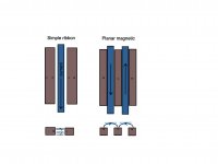
I think part of the confusion may arise because the orientations of magnets in planar magnetic drivers is a bit counterintuitive. Simple ribbons are easier to visualize. I threw together a really quick sketch to see if it helps: ribbon on the left, planar magnetic on the right. The upper pair of sketches show the front view, the bottom pair show the end view. Blue indicates the conductors. Black lines indicate magnetic field lines.
The trick is that you need to identify three mutually perpendicular directions. If the current in the conductor travels along x, and the magnetic field lines are parallel to y, the conductor feels a force along z.
The planar magnetic sketch shows a single-sided arrangement. You’d need a similar set of magnets, but mirror-imaged, on the other side of the conductors to create a push-pull arrangement. The field lines would still be along roughly the same directions where the conductors sit, but “compressed” a bit by the opposing magnets.
This was hastily thrown together so let me know if too may corners have been cut.
Few
Attachments
In the nonexistent ideal world, yes. Unfortunately, the straight lines in my sketch are an oversimplification. They bend more and more as you move away from the line connecting the midpoints of the magnets. If the magnets are far apart, this becomes more problematic. If the ribbon is 1/4” wide then you’re probably set. If it’s 1” wide then the field felt by the diaphragm will not be uniform. Some parts will feel more force than others, and pistonic motion is out the window.
Few
Few
No I accidentally deleted my last post, sorry.
So it seems that the only way to do what I want to do while being able to go "wide" is to build an array of ribbons that are very close to each other.
Seems doable though, Neo magnets can be ultra thin, like a couple of mm. Stacking them for height while maintaining thinness might be an issue though.
What do you think?
Last edited:
We wish that one worked but it doesn't work well. I have built a number of protos of that arraignment, even a curved array of large 2 inch wide ribbons. It was 24 inches wide by 40 inches tall. Also similar in 1 inch and 1/2 inch wide ribbons. They were OK for treble ( actually not all that great for that eather) but bass and midrange is soft and weak. Far too many issues with loss of dynamics from standing wave cancelation issues AND the gap between ribbon edges and magnet faces.
The simple planers ive built, even the ones with magnets spread out waayyy too far were superior to the "ribbon array". Way better dynamics.
The simple planers ive built, even the ones with magnets spread out waayyy too far were superior to the "ribbon array". Way better dynamics.
Last edited:
a magnet a few mm wide will have no field strength even a little ways away. and standing waves in a long thin structure are going to happen at lower frequencys no matter how thin
so the thinner magnets will dictate a less wide ribbon so now your into a larger number of air gaps between ribbon edges and magnet creating even more loss of low freq pressure.
the theory is solid but years ago I forged ahead on just such designs and found out the hard way that it doesn't work
so the thinner magnets will dictate a less wide ribbon so now your into a larger number of air gaps between ribbon edges and magnet creating even more loss of low freq pressure.
the theory is solid but years ago I forged ahead on just such designs and found out the hard way that it doesn't work
Last edited:
- Home
- Loudspeakers
- Planars & Exotics
- Ribbon desktop speakers?