So I've been playing with a quasi-ribbon idea. The concept is to use some higher permeability material than AL for the 'ribbon', to get a more even flux level in a wider gap. I've only seen the notion of a magnetically soft ribbon mentioned a couple of times, and in both cases dismissed. I couldn't figure out why, and FEMM plots looked promising, so I decided to try it.
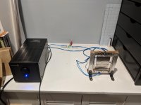
I used 50 micron self-adhesive mu metal foil and stuck a 3" x 5" strip of it on to a tensioned Mylar sheet. I intended to have AL frames on both sides of the Mylar holding Neo bar magnets, but enough of my magnets flew into each other and shattered, that tonight's test only had magnets on one side. Not to mention holes in the Mylar covered by yes, that's Scotch tape in the picture. Working with steel tools and hardware around those Neo mags is brutal!
And no transformer yet - I stuck a 6 ohm resistor in series and cranked up the source (my phone) and amp (a Parts Express APA150) to max, and said let's see.
And well, I could hear it. Just. About a foot from the membrane, and no bass, but hey, all things considered I'll take it!
So I'm in the market for a suitable transformer, first of all. And they aren't jumping out at me in search results. Suggestions? I was considering ordering a Fountek Neo 3 and harvesting it, as it seems to have the 20:1 ratio that would get me to 8 ohms. Or their pro version, which claims higher power handling. But it's a bit more than I'd like to shell out without knowing how well the repurposing could go.
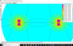
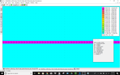
FEMM seems to think the idea will scale up fine - the second set of screenshots is an 8" gap. And uses a higher saturation material. Note the steel there is not for magnetic-circuit purposes, it's just part of a planned more elegant, glueless frame.
So...what am I missing? I'd expect plenty of normal sorts of issues in trying to make this work decently, but I still don't see why it's so obviously doomed. Of course what I don't know about magnetism fills volumes! Is there some gotcha looming under dynamic conditions? Or maybe being capped at ~2 T is just going to be too limiting, given the mass increase. Hmmm, actually...comparing some conventional midrange drivers' BL specs...maybe that's it.
Well, I'm going to build myself a pair of them, anyway! Hope it's of some interest, and thanks for any insights.
-Patrick
I used 50 micron self-adhesive mu metal foil and stuck a 3" x 5" strip of it on to a tensioned Mylar sheet. I intended to have AL frames on both sides of the Mylar holding Neo bar magnets, but enough of my magnets flew into each other and shattered, that tonight's test only had magnets on one side. Not to mention holes in the Mylar covered by yes, that's Scotch tape in the picture. Working with steel tools and hardware around those Neo mags is brutal!
And no transformer yet - I stuck a 6 ohm resistor in series and cranked up the source (my phone) and amp (a Parts Express APA150) to max, and said let's see.
And well, I could hear it. Just. About a foot from the membrane, and no bass, but hey, all things considered I'll take it!
So I'm in the market for a suitable transformer, first of all. And they aren't jumping out at me in search results. Suggestions? I was considering ordering a Fountek Neo 3 and harvesting it, as it seems to have the 20:1 ratio that would get me to 8 ohms. Or their pro version, which claims higher power handling. But it's a bit more than I'd like to shell out without knowing how well the repurposing could go.
FEMM seems to think the idea will scale up fine - the second set of screenshots is an 8" gap. And uses a higher saturation material. Note the steel there is not for magnetic-circuit purposes, it's just part of a planned more elegant, glueless frame.
So...what am I missing? I'd expect plenty of normal sorts of issues in trying to make this work decently, but I still don't see why it's so obviously doomed. Of course what I don't know about magnetism fills volumes! Is there some gotcha looming under dynamic conditions? Or maybe being capped at ~2 T is just going to be too limiting, given the mass increase. Hmmm, actually...comparing some conventional midrange drivers' BL specs...maybe that's it.
Well, I'm going to build myself a pair of them, anyway! Hope it's of some interest, and thanks for any insights.
-Patrick
Attachments
-
 Quasi-Ribbon_test_setup.jpg813.2 KB · Views: 318
 -
 FEMM_Ans_As_Tested.png145.6 KB · Views: 326
 -
 Gap_Flux_As_Tested.png83.9 KB · Views: 306
 -
 Hypothetical_Higher_Saturation_8inchGap.png84.5 KB · Views: 305
 -
 Hypothetical_Higher_Saturation_8inchGap_FEMM_Ans.png117.9 KB · Views: 301
 -
 Hypothetical_Higher_Saturation_8inchGap_Gap_FLux.png81 KB · Views: 83
well you lose output when you make it more heavy, also i dont have any clue why to use any other material then aluminium ") best weight to conductivity ratio.
best weight to conductivity ratio.
1.5 tesla over 10 cm ? that looks almost to good to be true or the magnets are insane big, i must be mistaken by the size of those neos i think, thats a dangerous looking setup. if glue or that screw cant hold those they will be flying. and you might have had luck a few times but if a piece of neo enters your eye, shes gone, it is sharp as hell.
i dont think you can make a 8 inch gap with 1.5 tesla. something loooks weird here.. a perfectly flat 1.5 tesla over 10 cm, what are the magnets size ?
best weight to conductivity ratio.1.5 tesla over 10 cm ? that looks almost to good to be true or the magnets are insane big, i must be mistaken by the size of those neos i think, thats a dangerous looking setup. if glue or that screw cant hold those they will be flying. and you might have had luck a few times but if a piece of neo enters your eye, shes gone, it is sharp as hell.
i dont think you can make a 8 inch gap with 1.5 tesla. something loooks weird here.. a perfectly flat 1.5 tesla over 10 cm, what are the magnets size ?
...thats a dangerous looking setup. if glue or that screw cant hold those they will be flying. and you might have had luck a few times but if a piece of neo enters your eye, shes gone, it is sharp as hell.
Yeah, point taken! The two-part epoxy I'm using (3M 8805) is supposed to be crazy strong, but the Neo's coating is slick, and under constant force, I guess have to expect it to fail eventually. I will plan for safe disassembly in the near term. Hopefully the 410 steel on the inside will be safer as well as less ugly. (Simmed 416 because it was in the library, and not critical, I think.)
i dont think you can make a 8 inch gap with 1.5 tesla. something loooks weird here.. a perfectly flat 1.5 tesla over 10 cm, what are the magnets size ?
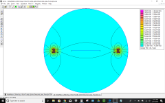
In that sim, they are one N52, 4" x 1/2" x 1/4", on each side. Actually the 4" is into the page so not modeled.
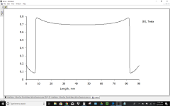
Note in all these cases, the high flux is *only* inside the 50-100 micron high mu material, not the whole gap. But it seems to hold up (inside the material only) under reasonable excursion.
It's quite possible I have some setting wrong in FEMM. Problem depth is set to 1mm, and if I recall that can affect scaling. But that should be okay? Are there other scaling parameters that I might have set wrong?
Thanks for the sanity check....that's part of why I'm here!
-Patrick
Don´t plot the abs field.
It is the tangential field that is of interest in your case.
The horizontal field should be very near to zero.
I did a quick simulation with N42 magnets, I get Bx = 0.016 T in the middle of 100 mm gap.
Thanks for the sanity check. I agree the Bx component is the relevant one; this is a top down view with current in/out of the page and force to be towards top/bottom of the page. But I do get 1.5 T Bx inside the 2 T saturation, high mu_r material. I had to enter the BH curve for the Thorlabs product by hand, so it's possible I made a mistake. Switching to the mu metal that came pre-defined in FEMM, I get the same sort of result, but now at ~0.68 T level.
Did you define the new material, and take output from within it (not just anywhere in the gap?) Conversely, is there some FEMM setting that could be mis-scaling my output? Or, am I fundamentally off base in thinking that B inside the conductor suffices? Do we, for some dynamics reason, have to have the constant B in the -air- around the conductor actually? I've looked briefly at excursion cases, and the high flux level seems to track the material for say 4 mm peak excursion (so, still very much between the magnets). Although I do need to look at direction more closely in that case.
-Patrick
Attachments
Last edited:
I get the same results.
I think FEMM can't handle that small area and thus gives the wrong plot.
If you probe inside the area with the point tool instead you'll get a field near zero.
I think that you should use "air" as the material between the magnets/pol pieces.
Thanks for looking at it, and the point tool tip. I'm working today but will take a look at that tonight.
Is there some physics or materials reason that we think the high mu material wouldn't concentrate and 'conduct' the B field as advertised? A thicker slab with small or no air gap to the magnets surely would, as in a closed magnetic circuit, right? So we just think the air gap is too far, and the foil is too thin, to concentrate so much? Not saying you're wrong, but understanding why & educating my intuition is likely to be the only fruit of this experiment, so I want to make sure I understand the rationale.
Thanks again.
-P
Congrats for building a ribbon driver from scratch. Building a driver is its own reward. I have built several configurations of ribbon tweeters/speakers. My suggestions and comments are:
Buy a magnetic field strength measurement instrument that that has a probe that fits into tight spaces. These cost real money. Unless you can measure a field, you mostly are building blind.
The largest gap that I think is practical is on the order of 1/2". Narrower is better.
For a ribbon, the idea of focusing the field will get you mostly nowhere. It is better to have some depth to the magnet and have the magnet as close to the diaphragm as possible. You get more B-field between the magnets the deeper the magnets are all else being equal. I built a focusing structure so I have a good A/B comparison.
I use only ceramic magnets. The exotic magnets are expensive and dangerous for DIY. If you can build with exotics unmagnetized and then magnetize the assembly, that would be good but who has the ability to do that magnetization?
There is very little to gain with the flux manipulation from the Mu ribbon AND there is a HUGE loss from its mass and resistance.
The ideal practical metal is aluminum.
Transformers for ribbons are far easier than most realize. All the hype about Amorphous metals and exotic winding goes out the window in these designs.
To experiment I would just order some ferrite cores from Digi Key similar to this..
ETD59/31/22-3C97 Ferroxcube | Magnetics - Transformer, Inductor Components | DigiKey
and get some magnet wire from similar places, and wind your own by hand. Keep leads to ribbon short ( and or close together), and use foil .0007 inch thick or less on ribbon and you can easily get response to 20 K hz.
Good place to start is 24-20 gauge primary wire and just parallel 4-6 of those for your secondary or use copper foil ( about .005 to .008 in thick). Many ribbon transformers have about 50- 70 turns pri and 3-5 turns secondary. Dont fuss too much here. That last statement will start a fire with some. Perhaps they have special ears but Ive been doing this for 30 years and have all the different transformer designs at my disposal. The standard simple winds and silicon iron or even cheap ferrite cores stand toe to toe with the exotics in low resistance ribbon design. The ribbon diaphragm design MUCH more important
There is nothing special going on in commercial ribbon transformers. Dont get swayed by the hype, roll your own
THE issue with a good ribbon is 90% in the ribbon diaphragms design/build. This is where the hard work is. Getting a smooth glitch free response all the way out with a low crossover point in a design that can put up with abuse is a very rare thing.
Small narrow ribbons are easier to accomplish this ( but with higher crossover point ) BUT IMO the gold is getting a wider larger surface area ribbon ( not more than 1 inch wide) to do it so that a lower crossover point can be used.
The ideal practical metal is aluminum.
Transformers for ribbons are far easier than most realize. All the hype about Amorphous metals and exotic winding goes out the window in these designs.
To experiment I would just order some ferrite cores from Digi Key similar to this..
ETD59/31/22-3C97 Ferroxcube | Magnetics - Transformer, Inductor Components | DigiKey
and get some magnet wire from similar places, and wind your own by hand. Keep leads to ribbon short ( and or close together), and use foil .0007 inch thick or less on ribbon and you can easily get response to 20 K hz.
Good place to start is 24-20 gauge primary wire and just parallel 4-6 of those for your secondary or use copper foil ( about .005 to .008 in thick). Many ribbon transformers have about 50- 70 turns pri and 3-5 turns secondary. Dont fuss too much here. That last statement will start a fire with some
. Perhaps they have special ears but Ive been doing this for 30 years and have all the different transformer designs at my disposal. The standard simple winds and silicon iron or even cheap ferrite cores stand toe to toe with the exotics in low resistance ribbon design. The ribbon diaphragm design MUCH more importantThere is nothing special going on in commercial ribbon transformers. Dont get swayed by the hype, roll your own
THE issue with a good ribbon is 90% in the ribbon diaphragms design/build. This is where the hard work is. Getting a smooth glitch free response all the way out with a low crossover point in a design that can put up with abuse is a very rare thing.
Small narrow ribbons are easier to accomplish this ( but with higher crossover point
) BUT IMO the gold is getting a wider larger surface area ribbon ( not more than 1 inch wide) to do it so that a lower crossover point can be used.
Last edited:
Thanks Solhaga for the gear tip, and lowmass for the transformer encouragement! I was hoping somebody would chime in with that. Ok sure, I've already got magnet wire; for $6 why not have a go at winding a transformer.
I respect the many voices of experience saying the mu metal concept is a red herring, but I've got to go through the process of seeing for myself. Should be able to report empirical confirmation or disconfirmation of the FEMM results in 7-10 days.
I respect the many voices of experience saying the mu metal concept is a red herring, but I've got to go through the process of seeing for myself. Should be able to report empirical confirmation or disconfirmation of the FEMM results in 7-10 days.
conventional wisdom seems upheld...
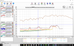
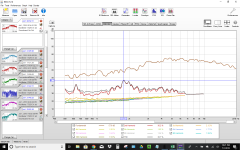
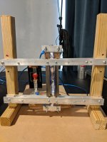
So, built a test bed and ribbons and got to measuring. The initial plan of mounting mu metal strips on Mylar to provide a greater Sd created too many variables to sort out the issues immediately, so I backed off to just looking at similarly sized ribbons of AL, Cu, and Mu metal at various magnetic air gap widths. And, long story short, so far it seems you all were right: "little to be gained by manipulating the flux", and greater mass and resistivity are killers. Resistivity may be more the problem with these Fe-Ni alloys than mass density, as it is worse by a factor of 20 compared to AL, versus "only" a factor of 3 for density. From looking at the transfer functions, M and R appear to be equally the enemy of SPL.
Specifically, the mu metal ribbons did not display the FEMM-promised insensitivity to gap width, except maybe they did not suffer quite as much loss in the move from 4" to 8" gap width as did AL. (I didn't repeat that one for copper.) Moot, because even the 4" output was not useable. Moving from almost no separation to 4" separation with the mu metal ribbon dropped the output level significantly (-30 dB or so IIRC), which means the idea is not working as hoped. I was surprised that AL made noise at all at 8" separation; but there was some signal to be heard even so, with the amp cranked.
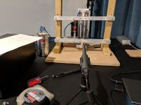
A few test bench pics and measurements are attached. I'm left wondering about the 1.7kHz 2nd HD peak the Mu metal and Cu ribbons display. The AL is just kind of ratty everywhere. Any 2HD diagnosis tips?
My other interpretation question is about the "baffle step" looking rise from 1k to 5k. But it's 20 dB not 6, and dipole roll off wouldn't plateau on the low end like that. Right?
The ribbons were all flat (uncorrugated), 0.5" x 4" (moving part between the clamps). AL was the thinner grocery store foil, 0.6 mil says Reynold's website, although it was the store's generic version. Copper was an adhesive conductive tape not much thicker than the AL, but folded in half from 1" to the 0.5" width, doubling thickness. Mu metal was 50 micron, thinnest I could source. Measurements were on-axis horizontally, maybe an inch below axis vertically, at 10" distance. In the pics, the AL ribbon (blue edges) is shown in the minimal gap, magnets to the inside configuration; the mu metal ribbon is shown in a whimsical, magnets turned to the outside of the 'narrow gap' post position. The other two sets of holes in the crosspieces are the 4" and 8" widths.
I may keep playing around with variations, since the overhead of building the test bed is already done. And correlating measurements to math model to better understand expected performance. Wish I understood in detail why FEMM results were misleading. The adventure continues.
Cheers,
-P
So, built a test bed and ribbons and got to measuring. The initial plan of mounting mu metal strips on Mylar to provide a greater Sd created too many variables to sort out the issues immediately, so I backed off to just looking at similarly sized ribbons of AL, Cu, and Mu metal at various magnetic air gap widths. And, long story short, so far it seems you all were right: "little to be gained by manipulating the flux", and greater mass and resistivity are killers. Resistivity may be more the problem with these Fe-Ni alloys than mass density, as it is worse by a factor of 20 compared to AL, versus "only" a factor of 3 for density. From looking at the transfer functions, M and R appear to be equally the enemy of SPL.
Specifically, the mu metal ribbons did not display the FEMM-promised insensitivity to gap width, except maybe they did not suffer quite as much loss in the move from 4" to 8" gap width as did AL. (I didn't repeat that one for copper.) Moot, because even the 4" output was not useable. Moving from almost no separation to 4" separation with the mu metal ribbon dropped the output level significantly (-30 dB or so IIRC), which means the idea is not working as hoped. I was surprised that AL made noise at all at 8" separation; but there was some signal to be heard even so, with the amp cranked.
A few test bench pics and measurements are attached. I'm left wondering about the 1.7kHz 2nd HD peak the Mu metal and Cu ribbons display. The AL is just kind of ratty everywhere. Any 2HD diagnosis tips?
My other interpretation question is about the "baffle step" looking rise from 1k to 5k. But it's 20 dB not 6, and dipole roll off wouldn't plateau on the low end like that. Right?
The ribbons were all flat (uncorrugated), 0.5" x 4" (moving part between the clamps). AL was the thinner grocery store foil, 0.6 mil says Reynold's website, although it was the store's generic version. Copper was an adhesive conductive tape not much thicker than the AL, but folded in half from 1" to the 0.5" width, doubling thickness. Mu metal was 50 micron, thinnest I could source. Measurements were on-axis horizontally, maybe an inch below axis vertically, at 10" distance. In the pics, the AL ribbon (blue edges) is shown in the minimal gap, magnets to the inside configuration; the mu metal ribbon is shown in a whimsical, magnets turned to the outside of the 'narrow gap' post position. The other two sets of holes in the crosspieces are the 4" and 8" widths.
I may keep playing around with variations, since the overhead of building the test bed is already done. And correlating measurements to math model to better understand expected performance. Wish I understood in detail why FEMM results were misleading. The adventure continues.
Cheers,
-P
Attachments
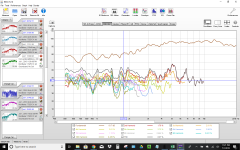
could be a number of things going on
1- to get accurate comparisons of HD you will need to use the exact same setup for each ribbon AND adjust amp so that you have the same loudness for each at around 1 Khz. This means the heavyer ribbons will need a lot more watts to keep up with the AL ribbon.
2- Peaks in distortion plots are usually resonances in the ribbon. The heavyer ribbon look better damped BUT have issues at certain areas. However again u will need to get their volume matched to the AL ribbon to really know.
3- To see the peaks change just grab one end of the ribbon and change its tension. Or corrugate and see where the peaks are. Also pull on corrugated version and watch the peaks change position as the corrugations size is changed by pulling ribbon.
4- the rise in responses is typical low mass diaphragm response.
5- also the different ribbon resistances, IF all used with same transformer wil yeald very different resistance to your amp wich may or may not give some change in high freq response. Some times to see actual response of a ribbon I will get rid of transformer and just run a resistor making all the ribbons same resistance.
could be a number of things going on
Wow, thank you lowmass, that's all great intel!
- Status
- This old topic is closed. If you want to reopen this topic, contact a moderator using the "Report Post" button.
- Home
- Loudspeakers
- Planars & Exotics
- Quasi-Ribbon Experiment, take 1