I am gathering drivers and parts for my next speaker project and one of these is a pair of Dayton AMTPRO-4 AMT. After doing some modeling I plan to use this without the pads and located at the top of an open baffle, about halfway in/out of the baffle (the unit will stick out halfway above the baffle with the lower half mounted in the baffle). This seems to result in good CD-like off-axis response.
I thought I would try to get some opinions from people on just how low I can cross over to the woofer with this arrangement. There should be a little more low end support in the frequency response when it is partially in the baffle. The infinite baffle response is usable down to 800Hz, but I am thinking 1kHz might be possible. Would that result in too much strain on the driver?
The crossover and speaker are both active, so I can shape/EQ the driver's frequency response as needed.
Mine measured very low distorsion. But what about "the sound"... I wasn't so sure. But I'll keep them for future endeavours. A rock-box sealed back for the ATM and a smaller seald for a 15" with a Hypex 2x400W inc. X-over plate amp :-D
CL - what did you think about the SQ? Do they improve by time?
//
CL - what did you think about the SQ? Do they improve by time?
//
OK, here are my measurements on the AMTPRO-4. I collected all this data by suspending the driver in free air and using gated impulse measurements. I was able to get about 50Hz frequency resolution using this approach. For the HD and IMD measurements I did not check the level but I would estimate that it was at least 90dB@1m with the "10dB louder" HD measurement increased by that amount.
Attachments:
Conclusions:
This is a unique driver in that the front and rear frequency responses are similar, and the rear response is without peaks or nulls above 2kHz (this is often a problem with a cone driver because of the magnet and backet). Because of the length of the diaphragm the vertical response is already starting to narrow around 2k-3k Hz but this is about the only shortcoming of the driver when used in this way. The distortion is pretty low between 1kHz and 8kHz and this distortion profile remains about the same when you increase the SPL another 10dB. IMD also looks good. Based on the harmonic distortion plot I think one could use this driver down to 1.5kHz if crossed steeply. Where to cross over to a tweeter depends on how close you want to get to the high end distortion rise, narrowing response pattern and diverging response between front and rear.
NOTE: to figure out which plot is which, hover the mouse pointer over the attachment thumbnail and then look for the name at the bottom of the browser window.
.
Attachments:
- Horizontal FR at 0deg and about every 11 degrees off axis until 90 deg, taken in FRONT of the driver at a distance of 16inches (0.4m)
- Horizontal FR at 0deg and about every 11 degrees off axis until 90 deg, taken in BACK of the driver at a distance of 16inches (0.4m)
- Vertical FR at 0deg and about every 11 degrees off axis until 90 deg, taken in FRONT of the driver at a distance of 16inches (0.4m)
- Vertical FR at 0deg and about every 11 degrees off axis until 90 deg, taken in BACK of the driver at a distance of 16inches (0.4m)
- Harmonic Distortion vs frequency on axis in front at 16inches (0.4m)
- Harmonic Distortion vs frequency on axis in front at 16inches (0.4m), with level increased by 10dB
- IMD (using 10kHz and 11kHz tones) on axis in front at 16inches (0.4m)
Conclusions:
This is a unique driver in that the front and rear frequency responses are similar, and the rear response is without peaks or nulls above 2kHz (this is often a problem with a cone driver because of the magnet and backet). Because of the length of the diaphragm the vertical response is already starting to narrow around 2k-3k Hz but this is about the only shortcoming of the driver when used in this way. The distortion is pretty low between 1kHz and 8kHz and this distortion profile remains about the same when you increase the SPL another 10dB. IMD also looks good. Based on the harmonic distortion plot I think one could use this driver down to 1.5kHz if crossed steeply. Where to cross over to a tweeter depends on how close you want to get to the high end distortion rise, narrowing response pattern and diverging response between front and rear.
NOTE: to figure out which plot is which, hover the mouse pointer over the attachment thumbnail and then look for the name at the bottom of the browser window.
.
Attachments
-
 Dayton AMTPRO-4 0-11-22-33-44-55-67-78-90deg 16in front.PNG41.3 KB · Views: 1,643
 -
 Dayton AMTPRO-4 0-11-22-33-44-55-67-78-90deg 16in rear.PNG43.3 KB · Views: 1,604
 -
 Dayton AMTPRO-4 0-11-22-33-45deg 16in front vertical.PNG35.8 KB · Views: 1,691
 -
 Dayton AMTPRO-4 0-11-22-33-45deg 16in rear vertical.PNG37 KB · Views: 1,643
 -
 Dayton AMTPRO-4 distortion at 16in.PNG45.2 KB · Views: 1,564
 -
 Dayton AMTPRO-4 10dB louder distortion at 16in.PNG44.3 KB · Views: 759
 -
 Dayton AMTPRO-4 10k 11k IMD at 16in.PNG27.1 KB · Views: 756
Last edited:
A few years ago, I concluded it made no sense to lock-into the details of crossing-over before putting a mic at your seat and choosing freq and maybe slope empirically with REW, at least as far as the bits and pieces and components I fool with.
Just as nobody makes a car with windows with manual winders (I think), so it makes little sense today for music enthusiasts to make their main system anything but a multi-amped system with an adjustable crossover.
B.
Just as nobody makes a car with windows with manual winders (I think), so it makes little sense today for music enthusiasts to make their main system anything but a multi-amped system with an adjustable crossover.
B.
Wonder if people are using these with no tweeter above their FR and just EQing?
I'm going to assume yes and "to heck with the added 2nd-order distortion up-to and around 10-12k".
I bought a pair of these, but because they weren't what I was expecting, may be selling them...
I'm going to assume yes and "to heck with the added 2nd-order distortion up-to and around 10-12k".
I bought a pair of these, but because they weren't what I was expecting, may be selling them...
Last edited:
To reply to TNT's old question:
"I wonder why people seem to not really take a liking on them?"
I got a pair. They were OK, but didn't work for the niche application I had in mind. I wanted to make a high efficiency coaxial by removing the faceplate
(this thread shows what they look like without it):
AMT tweeters - explored by Critofur -
Techtalk Speaker Building, Audio, Video Discussion Forum
...and mounting them in the mouth of a midrange horn. I was using some big JBL compression drivers, and I wanted to use the AMTs to fill in the range where the JBLs were spiky.
For me, the vertical dispersion of the AMT was too narrow to work well in this setup. For an always seated listener, it might have been fine.
In general:
- these particular AMTs take a bit of eq to flatten.
- if you use a big planar as a wide range driver (up to 10kHz), the vertical dispersion will be quite limiting.
- IF you use them only in the midrange (1-5kHz), the dispersion would be fine, but there are tons of reasonably priced conventional and horn drivers that do 1-5kHz happily. The only reason to choose the AMT over them is if you were into the dipole thing.
I'm glad that this thread popped up again! I had a hard drive crash this year, and unfortunately I found that the last backup I did was in 2016 (doh!), so I lost about four years of work including these measurements. I forgot I posted them.
I never found a good application for this driver that wasn't handled better by another driver. The low end is limited, strictly by the frequency response, but also by the rising distortion below about 1.1kHz. So you have to use it much like a tweeter. But the limited on axis high end extension, and the poor off axis response, makes it a poor choice to go "all the way up" to 20kHz or wherever your hearing ends. This means you would need yet another driver to take over around 3k-5k Hz before the beaming gets too bad. This is a pretty narrow range of potential applicability for a driver of this cost level.
Like Hollowboy mentioned, there are just too many other less expensive and better performing drivers than this one out there. Although mid-band distortion is low, IMHO Dayton squandered their opportunity in the AMT/planar market with this driver.
Bringing this thread back from the dead, again
"The low end is limited, strictly by the frequency response, but also by the rising distortion below about 1.1kHz." - maybe there was some problem with your test? Another chap posted distortion plots, back in 2013, that didn't have these big spikes.
AMT tweeters - explored by Critofur -
Techtalk Speaker Building, Audio, Video Discussion Forum
"IMHO Dayton squandered their opportunity in the AMT/planar market with this driver." - the measured results indicate that the Dayton units are about as good as the premium (Beyma) drivers.
On 3rd party tests, the Dayton is just as flat, and goes substantially lower than the $500 Beyma TPL-150H. The Beyma is a lot more efficient, but this gap would close if you put the Dayton unit on a horn.
I'm thinking of pulling my pro4's out of storage and trying them again (if I can find them!), with tweaks like RAAL-style foam pads to control directivity. Maybe I can resurrect them as pure mids, e.g. 1-5kHz.
Attached pix: critofur's measurement of the pro4 (from the Parts Express forum) & Joseph Crowe's measurement of the Beyma TPL-150H (from his blog), which, as he notes, "does NOT match the manufacturer's published frequency response".
Attachments
Last edited:
"would it make sense to only use a smaller part of the diaphragm"
Yes, I think so - variations of this are used in some commercial devices.
The RAAL solution is to cover the ends of the dia with foam. This blocks HF, allows LF through.
Effect shown in this thread:
Raal 70-10 Deflector Pads effects -
Techtalk Speaker Building, Audio, Video Discussion Forum
Some Mundorf units intentionally make the device / faceplate asymmetric. I assume this improves response by breaking up the destructive HF interference.
Mundorf AMT25D Tweeters 6 Ohm AMT25D1.1, 543,60 €
Both of these are fairly gentle tweaks.
"and load it with a waveguide or horn"
Again, yes, I think so.
CharlieLaub's horizontal polar plots (1st attachment in post 5) of the AMTPRO-4 are pretty odd in the 1-5kHz range. A waveguide might improve this.
...so my plan is to try both of these ideas. I can rig a crude test horn up from cardboard (or maybe just angled "wings"), so it won't cost me anything to try it.
The Dayton AMTPRO-4 seems to be used in this commercial offering with an interesting construction/frame around it that seems to be open to the front and back:
ABACUS electronics - Oscara 210
Here it is used as well in a waveguide:
Quasikoax 1 Dokumentation - PDF Free Download
I´ve seen at least one more project where it was used in a waveguide as well but can´t find anymore. Just goes to show that this is maybe the best way!?
ABACUS electronics - Oscara 210
Here it is used as well in a waveguide:
Quasikoax 1 Dokumentation - PDF Free Download
I´ve seen at least one more project where it was used in a waveguide as well but can´t find anymore. Just goes to show that this is maybe the best way!?
I assume this improves response by breaking up the destructive HF interference.
I dug my drivers out of storage, and gave this a go. For the LF and distortion, I measure roughly similar results to these:
AMT tweeters - explored by Critofur -
Techtalk Speaker Building, Audio, Video Discussion Forum
...but for HF, I got the same hump centred at 10kHz that CharlieLaub measured.
Taping over some of the slots (to make the radiating area less symmetric) smoothed the response and partially flattened that 10kHz hump.
Using foam to mask the driver ends extended the HF, but only a little (about 1.5kHz).
I then used ~4dB of digital EQ to cut the remnants of the bump. The result of the 3 tweaks was flat from 800Hz to 16kHz.
Huge caveat:
This was true only for a close (50cm) on-axis mic.
For actual listening from a couple of metres away, the tweaks seemed to do nothing for dispersion. I got one configuration to sound quite good, but only when right on axis.
an interesting construction/frame around it that seems to be open to the front and back
That appears to be just for attaching grill cloth to (cosmetic only).
a waveguide [...] maybe the best way
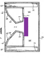
Probably something like this. To make them usable (for me), it'd need some type of horn that improves the dispersion.
i.e. one that has a diffraction slot to spray the HF around a bit, like in this picture I hacked together.
Attachments
Last edited:
I dug my drivers out of storage, and gave this a go. For the LF and distortion, I measure roughly similar results to these:
AMT tweeters - explored by Critofur -
Techtalk Speaker Building, Audio, Video Discussion Forum
...but for HF, I got the same hump centred at 10kHz that CharlieLaub measured.
Hmmm, I wonder if I accidentally built an artifact into my measurements around 1kHz? It's hard to say at this juncture, but it seems possible because I used such a long window. I still have the drivers somewhere since I never could come up with a good application for them.
Can you post your measurements?
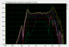
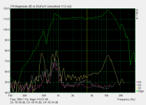
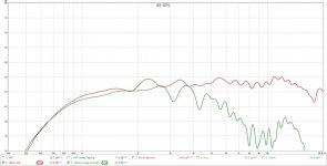
I just made some more measurements, all but the last are on axis.
They were done under hillbilly test conditions - mic tripod on a stack of milk crates in a cluttered room, SPL not calibrated. Bare driver (no face plate) perched on a stack of objects.
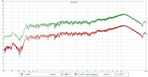
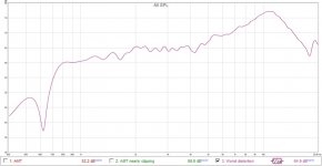
1) direct unsmoothed SPL plots @ about 35cm.
Red line is with about 15dB headroom, green with 1.4dB headroom (almost clipping).
This is not bad.
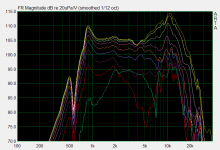
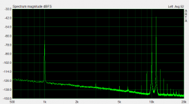
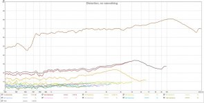
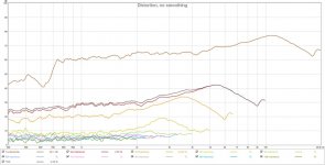
2) Distortion under the above loud condition (almost clipping).
PC fans and other ambient noise mean my noise floor is pretty high.
3) Distortion as above, but with bad gain structure: I turned REW down by 25dB, and turned the amp up by about 20dB.
The minor bulges you could see on (2) are now about four times as bad... so the distortion appears to be largely an artifact of my PC + amp.
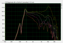
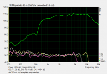
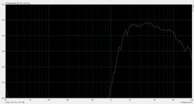
4) The SPL plot of the last test (bad gain structure), with windowing / smoothing to. I also zoomed in here - the grid is 5dB divisions, rather than 10dB.
It is very non-flat, but looks easy to fix / EQ.
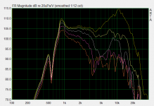
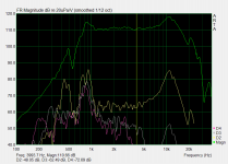
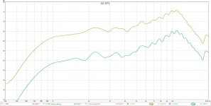
5) 20cm vs 1m SPL plot, with windowing / smoothing and same amp settings.
6) The same 1m SPL plot, as above, before and after applying EQ (-6dB centred at 10kHz).
It is indeed easy to EQ flat.
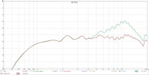
7) as above, mic on axis compared to mic raised by 30cm.
TL;DR:
The driver is well behaved, but only on-axis. As soon as you go off the vertical axis, the HF dies.
I assume this flaw / feature would be ~the same for any planer driver of these dimensions.
They were done under hillbilly test conditions - mic tripod on a stack of milk crates in a cluttered room, SPL not calibrated. Bare driver (no face plate) perched on a stack of objects.
1) direct unsmoothed SPL plots @ about 35cm.
Red line is with about 15dB headroom, green with 1.4dB headroom (almost clipping).
This is not bad.
2) Distortion under the above loud condition (almost clipping).
PC fans and other ambient noise mean my noise floor is pretty high.
3) Distortion as above, but with bad gain structure: I turned REW down by 25dB, and turned the amp up by about 20dB.
The minor bulges you could see on (2) are now about four times as bad... so the distortion appears to be largely an artifact of my PC + amp.
4) The SPL plot of the last test (bad gain structure), with windowing / smoothing to. I also zoomed in here - the grid is 5dB divisions, rather than 10dB.
It is very non-flat, but looks easy to fix / EQ.
5) 20cm vs 1m SPL plot, with windowing / smoothing and same amp settings.
6) The same 1m SPL plot, as above, before and after applying EQ (-6dB centred at 10kHz).
It is indeed easy to EQ flat.
7) as above, mic on axis compared to mic raised by 30cm.
TL;DR:
The driver is well behaved, but only on-axis. As soon as you go off the vertical axis, the HF dies.
I assume this flaw / feature would be ~the same for any planer driver of these dimensions.
Attachments
-
 AMT SPL plots 15dB from clipping and 1.4dB from clipping no smoothing no filter no nothing.jpg86.6 KB · Views: 283
 -
 AMT distortion 1.4dB from clipping.jpg72.9 KB · Views: 339
 -
 AMT with REW at -30dB and amp turned up.jpg74.1 KB · Views: 128
 -
 AMT with IR window and zoomed plot.jpg52.6 KB · Views: 115
 -
 AMT 20cm vs 1m on axis same amp settings.jpg56.2 KB · Views: 122
 -
 100cm with and without subtractive EQ.jpg55.9 KB · Views: 150
 -
 100cm mic on axis vs mic raised 30cm.jpg61 KB · Views: 151
Last edited:
- Home
- Loudspeakers
- Planars & Exotics
- Dayton AMTPRO-4: how low to cross when used open back?