Why solid state? Tubes and direct drive ESL is a perfect match.
My Beveridge is playing just awsome and you can see the schematics above nr:73
The tubes are dirt cheep and there is a lot of them... so what are you waiting for guys and girls?
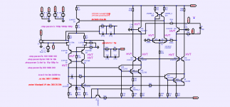
The schematics shown at post #73 contains some erratics :
Both bases of differential amp Q6 and Q7 are tied together, in this way they will output nothing.
Q4 and Q5 are fully shorted at all pins.
The schematics shown at post #73 contains some erratics :
Both bases of differential amp Q6 and Q7 are tied together, in this way they will output nothing.
Q4 and Q5 are fully shorted at all pins.
There's also the large capacitance across the 'transducer'. That can't be right.
It seems this is a schematic derived from a board, and it's very hard to do that right.
Jan
It does look odd , but actually is correct.There's also the large capacitance across the 'transducer'. That can't be right.
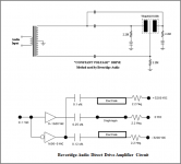
The transformer and direct-drive version of the Beveridge circuit topology are shown in attached pic.
This drive method enables you to get twice the voltage differential between the diaphragm and stators for a given amplifier output capability, so 2x the SPL. Essentially this is a form of amplifier bridging for ESLs. The downside is that it only works with highly conductive diaphragms.
It is very similar in concept to the Final “inverted” circuit arrangement.
More details and comparisons between the two methods posted here:
Beveridge vs Final ESL Configuration
Attachments
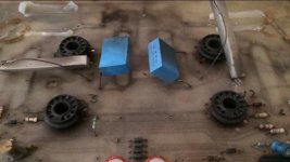
You do not need a lot of power to drive an ESL. The output impedance should be reasonable low because of the capacitive nature of the panels.
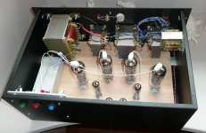
I have build many DD amps for more then 10 years now and all work stable. No tube failures so far and enough power to drive 8 Acoustat panels.
I suggest you start with the Beveridge amp as these tubes are very good and can be replaced by the PL509/519.
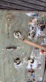
I do not like any solid state component therefor i replaced all transistors by tubes and omitted the filtering during prototyping.
Once you have a working amp you can add all the filtering you like.
To get a low output impedance you will have to add some (DC) feedback as this also stabilizes the DC bias on the output tubes and prevents runaway of the tubes.
I have build many DD amps for more then 10 years now and all work stable. No tube failures so far and enough power to drive 8 Acoustat panels.
I suggest you start with the Beveridge amp as these tubes are very good and can be replaced by the PL509/519.
I do not like any solid state component therefor i replaced all transistors by tubes and omitted the filtering during prototyping.
Once you have a working amp you can add all the filtering you like.
To get a low output impedance you will have to add some (DC) feedback as this also stabilizes the DC bias on the output tubes and prevents runaway of the tubes.
Attachments
Last edited:


FYI, I just learned that some of the ignition transformers for gas and for oil appliances produce voltages and currents that are of the right order of magnitude for the power supply of an amplifier that drives electrostatic loudspeakers directly. Microwave oven transformers may also be suitable. Needless to say, they are all quite dangerous.
About 40 years ago, I ran a transformer from a fuel-oil furnace as HV supply. The interface board had fancy HV caps and big resistors (remember when TV''s had CRTs?) and insulation spray and mostly isolated from chassis ground. Possibly dangerous but I was young(er), poorer, and wilder.FYI, I just learned that some of the ignition transformers for gas and for oil appliances produce voltages and currents that are of the right order of magnitude for the power supply of an amplifier that drives electrostatic loudspeakers directly. Microwave oven transformers may also be suitable. Needless to say, they are all quite dangerous.
An awkward way to make to HV bias today and not sure about amp power supply use.
I scrounged-up a great collection of stuff by repeat visits to the local "war surplus" stores when building my DD later 70's, an advantage of life in the big city. HV oil-filled caps, chokes of many sorts, transformers, fans,etc. often MIL-spec.
B.
Last edited:
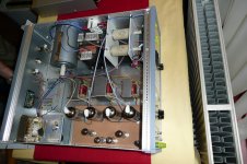
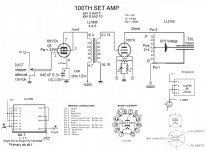
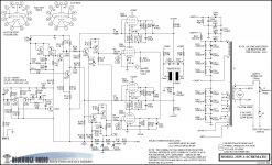
Attached are a couple of Direct Drive ESL schematics. The are both in the one amp with the right channel being SET and the left PP.
The PP gives way too much voltage and sparks my panels even with a diaphragm stator spacing of 3mm (with a bias voltage of 6000Vdc). The SET gives more than enough volume and my tube supply will last twice as long.
Some designers use parallel tubes to drive the 100TH as it takes grid current so I fitted 4 6HV5A sockets. I noticed from the LL1660 schematic that it can be wired as a 2:1 stepdown so I wired it that way and did not need paralled 6HV5A's.
The LL1660 interstages can be wired for either PP or SET but not the Anode chokes. The 25mA SET choke will work in PP but the PP choke with no air gap will saturate with the bias current.
The loudspeaker cables and the ESL panels are connected to the B+ voltage of 2880Vdc so the amp is best built as monoblocks located in the speaker enclosure.
These amp play every day and are stable.
A word of caution on the Eimac 100th tubes. I have ten faulty 100th tubes and just one good one. If an ebay seller does not accept returns do not buy them. You also need a means to check the Anode circuit as several of mine seem to have low vacuum glow blue and take too much current. A shorted tube will burn out the Anode chokes.
next step will be Amorphous core LL1660's and direct bias.
I use the amp as full range with no crossover or shelving equaliser. The SET works fine with plenty of volume so will wire the second channel as SET also
Attachments

Not mine, just Russian trace...
https://rcl-electro.ru/threads/Схем...-электростатических-наушников.392/post-101783
https://rcl-electro.ru/threads/Схем...-электростатических-наушников.392/post-101783
Attachments
Hi,
UnitedSIC, now qorvo, offer a couple of SIC-HV-JFETs with 1200V and 1700V drain voltage, as well as some enhancement mode SIC-MOSFETs.
While the former should lend themselves for simple H-bridged totempole designs, the latter are interesting because of their cascaded internal structure (enhancement MOS cascaded with a SIC-JFET).
I´d see the SIC-JFETs as cascoding devices within controlled current source topologies, but a simple SRPP-topology might suffice already.
UF3N170400B7s UJ3N120070K3S UF3C170400K3S UF3C120150K4S UF3C120080K4S UF3C120150B7S
attached is an intersting PDF about cascoding SIC-JFETs
jauu
Calvin
Attachments
A gentle bump to see if anyone knows anything about Rogers little babies? He was rightly very proud of these. There appear to be little transformers, or are they inductors, helping things along.Does the Modjeski direct drive amp use that circuit too?

[FONT=arial, helvetica]Output 4000 volts at 1/3 amps front to back electrode to electrode[/FONT]
Any thoughts?
Cheers
Gn
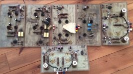
Here is the schematic I used when rebuilding my Beveridge amps. I can verify it is accurate, at least for my pieces ":^)
(there's actually still 1 error in the drawing, but the error also exists in the actual product - apparently a layout problem that wasn't solved yet, at least in mine)
I have HV scope probes and have measured the output; at clipping this puts out push-pull 2,500 Volts peak to peak with no load.
(there's actually still 1 error in the drawing, but the error also exists in the actual product - apparently a layout problem that wasn't solved yet, at least in mine)
I have HV scope probes and have measured the output; at clipping this puts out push-pull 2,500 Volts peak to peak with no load.
Attachments
- Home
- Loudspeakers
- Planars & Exotics
- Any Direct Drive ESL Amp projects someone could share?