KiCad is a commonly used free tool for PCB design. Some board houses take its files directly, which saves a little work.
It seems that all PCB design packages have their quirks. If you already know one and can get what you need from it, it may not be worth switching, unless you plan on doing a lot of that kind of work in the future.
It seems that all PCB design packages have their quirks. If you already know one and can get what you need from it, it may not be worth switching, unless you plan on doing a lot of that kind of work in the future.
@bengel: Hi ... I've used diptrace for some years and found it to be very intuitive and straightforward to use (they apparently aim for this in their development process). A free non-commercial version can be downloaded from here:
Download DipTrace - DipTrace
Cheers,
Jesper
Download DipTrace - DipTrace
Cheers,
Jesper
Mostly my complaint with fritizing is it is a pain when you have a new parts not in the library... thus you have attempt to create something from an existing part.
I'll give those a quick try but given I've spent alot of time designing/making PCB's with frizting, it may be better to stick to the devil I know") .
.
I'd like to do something with resistor boards also and post them to the forum. Such that folks can just upload gerber files to their favorite PCB manufacturer and get boards made.
I'll give those a quick try but given I've spent alot of time designing/making PCB's with frizting, it may be better to stick to the devil I know
. I'd like to do something with resistor boards also and post them to the forum. Such that folks can just upload gerber files to their favorite PCB manufacturer and get boards made.
Attached is a rough schematic where I landed on my bias supply. All caps are 3900 pF with 4000V diodes. There is a variable supply input not shown so 900VAC is the theoretical max coming out.
If I've calculated this all correctly, it gives me a max of ~5000Vdc (noted on the schematic). I thought about adding another stage but don't think I'll need to go higher than that.
I read some stuff in the forums about whether to positive or negative charge the diaphragm, is there any consensus on which is better? All I can find is dust concerns... which I have an electrostatic air filter for my house so even more likely dust will be negatively charged, so better to negative charge the diaphragm.
Soldering together the resistor banks now... Settled on a 52 kOhm segment resistance value crossing the panels somewhere in the 300hz area.
After all of that is done, step transformer board construction.
Currently debating building an L/R 24db analog active crossover (like I currently use). I like to stay analog as much as possible... seems ridiculous for my Marantz pre-pro to do all tha D/A conversion, then take that analog into a digital crossover, convert it to digital, split for the crossover - then output analog to feed the amp. But it's just so damn convenient to buy a digital crossover off the shelf.
If I've calculated this all correctly, it gives me a max of ~5000Vdc (noted on the schematic). I thought about adding another stage but don't think I'll need to go higher than that.
I read some stuff in the forums about whether to positive or negative charge the diaphragm, is there any consensus on which is better? All I can find is dust concerns... which I have an electrostatic air filter for my house so even more likely dust will be negatively charged, so better to negative charge the diaphragm.
Soldering together the resistor banks now... Settled on a 52 kOhm segment resistance value crossing the panels somewhere in the 300hz area.
After all of that is done, step transformer board construction.
Currently debating building an L/R 24db analog active crossover (like I currently use). I like to stay analog as much as possible... seems ridiculous for my Marantz pre-pro to do all tha D/A conversion, then take that analog into a digital crossover, convert it to digital, split for the crossover - then output analog to feed the amp. But it's just so damn convenient to buy a digital crossover off the shelf
.Attachments
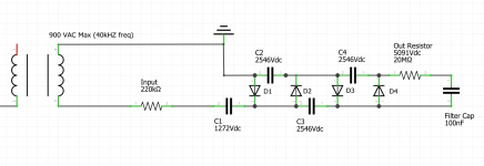
You don't typically see final filter caps across the output of ESL bias supplies, as the multiplier should be filtering reasonably well to produce DC. If you want one, placing it before the 20 megohm resistor seems like a better spot.
I have a cheap pro-sound analog crossover I use early in designs to get things up and running. I like to know how things play together before committing to build specific new stuff. Being able to dial in whatever frequency you want with a knob is a lot faster than dealing with most digital interfaces also.
I have a cheap pro-sound analog crossover I use early in designs to get things up and running. I like to know how things play together before committing to build specific new stuff. Being able to dial in whatever frequency you want with a knob is a lot faster than dealing with most digital interfaces also.
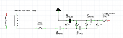
You are correct on the filter cap.. I made a mistake which I quickly realized when I was bread boarding it last night.
I just ended up deleting the filter cap. I used my oscilloscope to measure the output (at a much lower voltage obviously) and I couldn't see a hint of ripple.
(updated schematic attached)
The output is on the other end of the 20Mohm resistor to "ground". I get pretty good arcing between ground and the input side of the 20M resistor so I'll take that as a sign the voltage multiplier is doing its job. I get no arcing on the output side of the resistor (I kind of expect that) but I can hear that is wants to. Hopefully, I don't have too much diaphragm leakage.
I originally was going to put a neon lamp on the output, I actually have a couple of them. I seem to remember it had more of a purpose than merely showing the supply is running.
I'll take a look at the crossover stuff.... don't want to get too far ahead of myself. Like to make sure these panels will make good sound 1st.
I just ended up deleting the filter cap. I used my oscilloscope to measure the output (at a much lower voltage obviously) and I couldn't see a hint of ripple.
(updated schematic attached)
The output is on the other end of the 20Mohm resistor to "ground". I get pretty good arcing between ground and the input side of the 20M resistor so I'll take that as a sign the voltage multiplier is doing its job. I get no arcing on the output side of the resistor (I kind of expect that) but I can hear that is wants to
. Hopefully, I don't have too much diaphragm leakage. I originally was going to put a neon lamp on the output, I actually have a couple of them. I seem to remember it had more of a purpose than merely showing the supply is running.
I'll take a look at the crossover stuff.... don't want to get too far ahead of myself. Like to make sure these panels will make good sound 1st.
Attachments
For what it is worth, I am a Huge advocate in using a regulated Bias Supply.
I am always striving for that perfectness.
Regulated !!! ..... Not just one that you can adjust.
If you are using a CCF board regulation is as easy as a few resistors a dual opamp and a LM317 (sse the second sheet in the link below).
See this thread for more details,
how can test the stator insulation and mylar coating?
This is the addem I did due to a simple mistake in the schematic and can be ignored if you are using a pre assembled CCF board as mentioned.
how can test the stator insulation and mylar coating?
jer
Last edited:
I took at look at your schematics and can't figure out how it is doing that - but my electronics knowledge is pretty limited.
I had noticed when I was goofing around with my bias supply the DC voltage into the CCFL converter would fluctuate a little bit when it was arcing but always returned back to it's voltage set point (~12VDC).
I don't fully understand the royer oscillator circuit that steps up the 12VDC to 900VAC but if the DC input is well regulated, does that mean the HV output will be regulated as well?
I don't want to get too lost in the weeds at the moment but would be curious what a circuit would look like on the HV side of my setup to regulate voltage.
Sorry for the late reply, this is gonna be a long post....................
But I will do my best to keep it short sweet and simple ( ya this gonna be a bit longer). He, he,he
But First a little history of how this came about,
First off, I didn't know what a " royer oscillator circuit " was and had to look it up.
Yes, I did know what that circuit is but never knew it was called a " royer oscillator circuit ".
This does not use a royer oscillator even though it may look like one
Someone had mentioned it to me in recent days as well, so I will look into this type of circuit for future builds.
I was aware of it when I designed this thing but I wanted to use a LM555 timer and employ PWM with a single ended FET.
But there were several issues to overcome to make it work and this is how it ended up.
I was overwhelmed with how good the end product turned out and overall it is excellent if you don't mind me saying that, although there is plenty of room for refinement as well.
This was a product of necessity that came out of my tiny little brain that has a Huge Imagination !!
One of the criteria I had was it had to be created out of what I had as I had a Zero Budget< No Money At All, too buy any new parts for it, so it was all created out of parts in my junk bin including the transformer cores.
It was a Vast learning experience for me and gave me the opportunity further my knowledge of how transformers worked, to me they are very fascinating devices, there is a whole lot more going on the just knowing some turns ratio.
Speaking of transformer design and their operation see this thread for more on them,
Step-up transformer design
In the background you can see the Very First iteration of the supply as it was sprawled across the whole length of my desk, it was quite cumbersome but it worked nicely.
I believe at that time it was the single fet version and it got me up and running.
It would run quite hot and with not much power output for what it was worth, those details I will explain further as I go.
In my first setup as I mentioned (555 and single fet) I discovered that by varying the supply voltage the 555's output level and the single FET's output would change as well with it, but the frequency stayed stable at its set frequency so I stuck with this idea throughout.
Now being that the transformer was custom wound I found that it had a very high resonant frequency of about 180khz or more with a very sharp Q and any bit of the slightest deviation in the frequency would drastically change my output voltage level, so the 555 fit the bill at this point in time as it was finally working.
As for the 555 configuration it looks strange doesn't it !!?
For some reason this was the only way that I could make the 555 run at such a high frequency and only Bipolar type 555's will work like this.
I went through a few of them designing this and the CMOS versions will not work in this circuit, I tried them all !!
So, I do want to refine this part of the circuit eventually, but it works, and I kept KISS in mind throughout its whole creation.
This supply is still working to this day with only one early failure of one of the FET's, so I swapped them out for heartier ones as mentioned in the build thread.
jer
P.S. Now more on to its operation in the next post.
Last edited:
Anyhow,
Now that I had gotten the thing to work it was variable via my bench supply it was to be producing close to 9-10KV by the size of the arcs it was producing.
But it was very very inefficient and the FET was getting rather hot for the amount of voltage I was getting to drive the step up core, in which case was an filter toroid out of an old PC supply or something it was a pretty decent size one and the biggest one I had.
But it worked and quickly I realised that I needed to measure this voltage and started learning how to build a proper resistor divider and later on I discovered how much of an error that there can be when loaded by a meter.
At First I was using my scope since I had burned up all of my meters in the Transformer Design thread.
This was not an issue when using my 10x high impedance setting on my probe.
The supply at this point produced up to about 7.5KV unloaded.
With my little Desktop ESL's connected it dropped down to about 5.5-6KV and due to their leakage some of my older (painted) panels would only get as high as 4-4.5KV and later started to fail to the point of at 2-3KV I couldn't even get them to run without arcing and tripping the protection in my AWIA CD box as the transformer was producing more than what my bias supply was set at.
That was when I got my powder coated versions out and refurbished them.
Those I have tested with the final design fully assembled all of the way up to 13.8KV.
They measured up into the 12Kv range and you could hear the fan ramp up as there was about 1.8kv leaking out somewhere and the supply was compensating for it.
They held their own very well at 8-10KV, And of course, Until I sacrificed them as well in the name of Extreme R&D.
All of that those details are in various threads.
That bring us to the point of why this supply had to be regulated.
When I was able to finally get some nice low end response down to 30hz at a decent playable low level out of my huge stack of transformers, getting down below my resonant frequency of 70-90Hz was not an issue.
I was noticing on high excursions of the diaphragm it would cause the Bias Voltage to drop and fluctuate.
At times dropping as much as 500v to 1000v in some cases, the numbers are vague ( Hmm 10 years already! ) but it was like at least 10-15% on an average.
I saw even as much as 20% or better on my really bad panels !!
That is a pretty large range considering most people only use 2.5-4KV on their panels.
Leakage does attribute to this quite a bit depending on how well your panel is built.
My original painted design had all of this in mind but those ones really sucked !!
Paints were researched later in this thread,
High strength Dielectric Coatings, fact or fiction
And my method with tests are found here,
High strength Dielectric Coatings, fact or fiction
But, If your Bias Supply can't produce enough current to overcome those losses, that voltage will never be rock solid stable no matter how much capacitance you add to it's output !!
By the way it is exactly not cheap to do so either considering the amount capacitance you would need to filter out all of those low frequency power sag's, not to mention the supply's 60hz charging frequency of your average setup.
This is obviously an issue as I have read about such attempts before.
Solved that a long time ago !!
But honestly I never got the chance to measure these effects since I blew up the last set.
To me there was a very noticeable difference between from when I first started and the testing done with the new supply running properly.
Since then, I am back into this stuff again and plan to show my new setup running soon.
Everyone has already seen them partially built but they are not finished yet and the frames got broke and they have to be redone.
The last thing here is how the FET's are configured...........
It is just a basic classic ole Class B Linear Amplifier stage getting its full power directly off of the Filter Cap as shown on Page 1 at the top.
At the time I was truly inspired by Susan Parker amplifier design found here,
Zero Feedback Impedance Amplifiers
It made a lot of sense to me, so I used it, I would like to try this design as an ESL amp as well !!
It amplifies the signal coming from the 555 and its two transistor driver whose level is adjusted as previously mentioned by the LM317.
Next will be the Nitty Gritty, The operation and use of the opamp's in the feedback loop to control it.
Cheers !!
jer
Last edited:
Okay now that I have gone over the basic concept and the history of why this circuit came about I will walk you through the stages of the thing as too how this thing works as a whole.
But First, let's take a look at the data sheet of the opamp I used, the TL082, as we are at the mercy of what the opamp can produce overall.
There are better opamps to use but at the time the TL082 was all I had to work with.
Its data sheet is found here,
https://www.ti.com/lit/ds/symlink/t...rl=https%3A%2F%2Fwww.ti.com%2Fproduct%2FTL082
In future builds I plan on using ones from LT, I have been looking at some Rail to Rail types and possibly maybe using a chopper based stabilized device for even better accuracy.
But any good decent opamp will suffice here.
The TL082 has a typical voltage rating to be used at +/- 15V but it does have a maximum rating of +/-18V and on page 10 of the data sheet the graphs there show exactly how much voltage swing you can get out of the device.
In my case the results about 13.8- 14.2v peak with a 16V supply and corresponds to my maximum output setting at 13.8KV at 1V of control voltage to 1000V of DC output.
To get any more than this I would have to increase the number of multiplier stages and increase the loop gain to something like .5v in per 1000v out because the opamp simply cannot produce any more voltage than this.
So in order to get this high of a swing I had to set the power supply rails as close to max as possible that I could get it and to do this I choose not to use any regulators as commonly used in such circuits.
I didn't have any LDO types in that voltage range on hand and it would have added even more cost to the design as well if I would have had to get some, in fact they hardly even existed at the time and were just coming about.
So the next best thing was to use two diodes in series off of the main power rails at 17.82V, this gave me the needed 1-1.5v drop that I needed to be Just Below the 18v maximum rating of the TL082 to about 16V.
IIRCC earlier datasheets stated that 16V was the maximum but it is 18V I guess and supply headroom was the reason for concern, in fact I have blown up a number of the cmos type TLC082's before I had realized that there absolute maximum is at 16v and no more !! .... so stay away from those for this type of circuit unless you take its absolute maximum ratings into account.
This also gave me enough headroom from any line fluctuations from taking out the opamp due to overvoltages spikes.
I probably could have gotten away with a more conventional design using a common DC source but I built it in stages so I kept it the way it is.
I also felt that it gave me a little more protection for some reason by keeping the sections isolated from one another as well, thus the reason for so many diodes in the power supply section of this device.
Especially for the opamp's since they weren't regulated.
Now on with the gain structure.
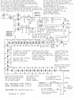
Starting at the top of page one you see two points " cntrl A & cntrl B" at the lM317 this is where feedback loop is inserted the magic begins !!
"cntrl A" is the output sense line of the LM317 and "cntrlB" is the control input to the LM317, all else is the same for any LM317 setup and is set at its highest possible voltage output.
Now down at the bottom of page 1 we'll look at the resistor divider stack.
This calculator came in extremely handy at this point,
Voltage Divider
In the earlier stages of design I was using about 100 megohms on the stack.
Even though this worked fine I found that it was producing more of an unnecessary load in the supply than I had liked, so I upped it to 300megohms.
Also with the smaller number of resistors in the string I was exceeding their voltage coefficient rating as well.
What this means is as you raise the voltage across the resistor its resistance at that voltage changes by X%.
I didn't take the time to measure this but I almost did since all of my resistors were from Radio shack and I could not find any data on them at all.
So I did the next best thing and searched out all of the resistors I could find and found them all to be in a range of 200v-350v for the 1/4 watt types and even found some as high as the 500v per resistor.
I choose 250V at my starting point and this put me well below that a 166.6V across each resistor at 5 KV and 300v at 10 kv and a max of 500v at 15Kv of voltage across the stack with 30x10megohm resistor stack.
As far as Power Dissipation loading of the stack it comes to 15KV^2/ 300,000,000 ohms at .75 watts for the whole thing !!
10 times under the rated 7.5 watts of 30 1/4 watt resistors in series and with only .5ma of current draw from the supply at 15KV !!
Now after all these decisions about voltages ranges and such, 15 & 14 were the magic numbers and by chance I had just happened to have an odd ball 7 volt regulator in my parts bin so I used that as my reference voltage to keep things simple, else I would have used a 5V regulator just the same.
Next finally the whole feedback thingy !!
jer
But First, let's take a look at the data sheet of the opamp I used, the TL082, as we are at the mercy of what the opamp can produce overall.
There are better opamps to use but at the time the TL082 was all I had to work with.
Its data sheet is found here,
https://www.ti.com/lit/ds/symlink/t...rl=https%3A%2F%2Fwww.ti.com%2Fproduct%2FTL082
In future builds I plan on using ones from LT, I have been looking at some Rail to Rail types and possibly maybe using a chopper based stabilized device for even better accuracy.
But any good decent opamp will suffice here.
The TL082 has a typical voltage rating to be used at +/- 15V but it does have a maximum rating of +/-18V and on page 10 of the data sheet the graphs there show exactly how much voltage swing you can get out of the device.
In my case the results about 13.8- 14.2v peak with a 16V supply and corresponds to my maximum output setting at 13.8KV at 1V of control voltage to 1000V of DC output.
To get any more than this I would have to increase the number of multiplier stages and increase the loop gain to something like .5v in per 1000v out because the opamp simply cannot produce any more voltage than this.
So in order to get this high of a swing I had to set the power supply rails as close to max as possible that I could get it and to do this I choose not to use any regulators as commonly used in such circuits.
I didn't have any LDO types in that voltage range on hand and it would have added even more cost to the design as well if I would have had to get some, in fact they hardly even existed at the time and were just coming about.
So the next best thing was to use two diodes in series off of the main power rails at 17.82V, this gave me the needed 1-1.5v drop that I needed to be Just Below the 18v maximum rating of the TL082 to about 16V.
IIRCC earlier datasheets stated that 16V was the maximum but it is 18V I guess and supply headroom was the reason for concern, in fact I have blown up a number of the cmos type TLC082's before I had realized that there absolute maximum is at 16v and no more !! .... so stay away from those for this type of circuit unless you take its absolute maximum ratings into account.
This also gave me enough headroom from any line fluctuations from taking out the opamp due to overvoltages spikes.
I probably could have gotten away with a more conventional design using a common DC source but I built it in stages so I kept it the way it is.
I also felt that it gave me a little more protection for some reason by keeping the sections isolated from one another as well, thus the reason for so many diodes in the power supply section of this device.
Especially for the opamp's since they weren't regulated.
Now on with the gain structure.
Starting at the top of page one you see two points " cntrl A & cntrl B" at the lM317 this is where feedback loop is inserted the magic begins !!
"cntrl A" is the output sense line of the LM317 and "cntrlB" is the control input to the LM317, all else is the same for any LM317 setup and is set at its highest possible voltage output.
Now down at the bottom of page 1 we'll look at the resistor divider stack.
This calculator came in extremely handy at this point,
Voltage Divider
In the earlier stages of design I was using about 100 megohms on the stack.
Even though this worked fine I found that it was producing more of an unnecessary load in the supply than I had liked, so I upped it to 300megohms.
Also with the smaller number of resistors in the string I was exceeding their voltage coefficient rating as well.
What this means is as you raise the voltage across the resistor its resistance at that voltage changes by X%.
I didn't take the time to measure this but I almost did since all of my resistors were from Radio shack and I could not find any data on them at all.
So I did the next best thing and searched out all of the resistors I could find and found them all to be in a range of 200v-350v for the 1/4 watt types and even found some as high as the 500v per resistor.
I choose 250V at my starting point and this put me well below that a 166.6V across each resistor at 5 KV and 300v at 10 kv and a max of 500v at 15Kv of voltage across the stack with 30x10megohm resistor stack.
As far as Power Dissipation loading of the stack it comes to 15KV^2/ 300,000,000 ohms at .75 watts for the whole thing !!
10 times under the rated 7.5 watts of 30 1/4 watt resistors in series and with only .5ma of current draw from the supply at 15KV !!
Now after all these decisions about voltages ranges and such, 15 & 14 were the magic numbers and by chance I had just happened to have an odd ball 7 volt regulator in my parts bin so I used that as my reference voltage to keep things simple, else I would have used a 5V regulator just the same.
Next finally the whole feedback thingy !!
jer
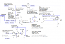
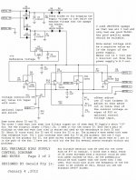
Okay here it is !!
I have redrawn the control section of this Power Supply design and I have included the original print as well for those of whom want to follow and compare.
I have omitted the opamp and driver power supplies from the print for easier reading.
It is pretty straightforward and the descriptions of the stages are on the print.
I plan on finishing this drawing to see if I can get Circuitmaker 2000 to simulate it for ease of future development as I have lost the original files.
If anyone would like to have a copy of the .ckt file I will post it in zip as it is not a supported file for some reason. 
I do know that some people like myself still use this old software and it can be found on the web if you search for it.
Else, one of these days I will reproduce it in LTspice as well since it is more common to use these days, not to mention more accurate for the most part.
I use it because I have had it for like forever since the 90's when I bought the original program for about a $1k that includes updates up until CM2000 was released, at which later I had found the key to unlock it after it was sold to Altera.
So, It is out there if one wanted to search for it.
I like LTspice but I find its editing features to be a bit cumbersome compared to CM2000 but it is more refined than CM2000.
Not to mention CM has its own PCB tools called Traxmaker and I use it a lot still, I used it to create the boards for this project as well and that is why I still keep it around.
CM2000 uses spice as well but sadly the program has been defunct since Altera bought it.
I don't know if it could be imported into the new Web version of Circuitmaker or not, I have not used the new version yet to find out as I don't much care for web based systems anyhow.
Cheers !!
Jer
P.S. I can't think of anything I have missed but if you have any questions, Please Do Ask !!
I am Back, and, I am here to help anyone with getting their DIY ESL's to work!!
Enjoy !!
I have redrawn the control section of this Power Supply design and I have included the original print as well for those of whom want to follow and compare.
I have omitted the opamp and driver power supplies from the print for easier reading.
It is pretty straightforward and the descriptions of the stages are on the print.
I plan on finishing this drawing to see if I can get Circuitmaker 2000 to simulate it for ease of future development as I have lost the original files.
If anyone would like to have a copy of the .ckt file I will post it in zip as it is not a supported file for some reason.
I do know that some people like myself still use this old software and it can be found on the web if you search for it.
Else, one of these days I will reproduce it in LTspice as well since it is more common to use these days, not to mention more accurate for the most part.
I use it because I have had it for like forever since the 90's when I bought the original program for about a $1k that includes updates up until CM2000 was released, at which later I had found the key to unlock it after it was sold to Altera.
So, It is out there if one wanted to search for it.
I like LTspice but I find its editing features to be a bit cumbersome compared to CM2000 but it is more refined than CM2000.
Not to mention CM has its own PCB tools called Traxmaker and I use it a lot still, I used it to create the boards for this project as well and that is why I still keep it around.
CM2000 uses spice as well but sadly the program has been defunct since Altera bought it.
I don't know if it could be imported into the new Web version of Circuitmaker or not, I have not used the new version yet to find out as I don't much care for web based systems anyhow.
Cheers !!
Jer
P.S. I can't think of anything I have missed but if you have any questions, Please Do Ask !!
I am Back, and, I am here to help anyone with getting their DIY ESL's to work!!
Enjoy !!
Attachments
Last edited:
With my little Desktop ESL's connected it dropped down to about 5.5-6KV and due to their leakage some of my older (painted) panels would only get as high as 4-4.5KV and later started to fail to the point of at 2-3KV
. . .
I was noticing on high excursions of the diaphragm it would cause the Bias Voltage to drop and fluctuate.
At times dropping as much as 500v to 1000v in some cases, the numbers are vague ( Hmm 10 years already! ) but it was like at least 10-15% on an average.
I saw even as much as 20% or better on my really bad panels !!
I feel like this probably belongs in a separate thread, but here goes anyway.
I don't understand how you are maintaining constant charge operation if you need your bias supply to put out large currents. What you're describing seems diametrically opposed to the methods used to produce a typical low-distortion ESL.
The amount of bias voltage required also seems abnormal, unless spacing is extreme.
Have you measured output vs various bias levels, sensitivity per unit area vs uninsulated stators, ultimate output vs. other insulation schemes, distortion at various drive levels, potential sensitivity shift after high drive levels, etc.?
Your description here sounds like you are overdriving your speaker, at which point bias decreases because you've exceeded the breakdown voltage somewhere. It sounds like you're then "fixing" that by supplying more bias current.
The other potential things that come to mind are: 1) perhaps your insulation is problematic (volume resistivity far too high so large portion of bias is lost across insulation) 2) you're shifting the sensitivity up by maximizing bias (but this provides no increase in ultimate output, as the audio signal level has to be decreased to compensate), or 3) you have leakage issues you're overcoming by supplying extra current (which over time may burn the diaphragm coating off in areas where it's happening).
Maybe I'm missing something or the answer is buried in a lengthy thread elsewhere, but I'm a bit lost given what's presented here.
Ya this should probably should be in another discussion thread as I don't want to be off topic about my projects, I am not in to hijacking other's threads, But I will try to answer your questions here anyhow.
#1,You don't need large currents to maintain a Constant Charge, this is a fact.
But as I stated when I saw the bias shifting it was before the regulation loop was added.
But if your panel is as leaky as some of my earliest ones were then that extra current comes in handy.
#2 I get this all of the time, " The amount of bias voltage required also seems abnormal" , what do you consider normal?
I can run "normal " voltages as well, the goal of my R&D was to see how far I could push the design and I got pretty far with it and it worked !!!
Despite everyone else's theories.
They ran for quite a while until one major flaw in construction destroyed one of them, that is documented in these threads.
OverDriven you say, Yep right to the point of getting flat topping of the sine wave as measured by my microphone.
At first I thought that I was clipping my then brand new dayton EMM-6 mic. but it was not.
I backed the mic off and it was still there, I later checked the limit of that mic and it was right in spec and would clip at 131db.
Now I like things loud besides, but this thing was scary loud !!!
This was in 2010.
I built the panels in 2003 and the only picture I have of them all together is found here,
Material for ESL
#3 Yes, I have measured the output vs various bias levels, you get an extra 6db of sensitivity every time you double the Bias Voltage, that is also document in these threads.
The amp really likes this as it means it now only has to output 1/4 of the power for the same SPL.
Ohms law says when you halve the voltage you are using 1/4 of the power for the same given load.
My THD above about 1Khz became unmeasurable to the limits of my soundcard at about .005% or better, that included any artifacts of what the step up transformer may or may not have been adding.
The worst cast that I had measured below 1Khz was with my Crown DC300a at full tilt and was about .5% to .2% THD and that was at about 330Hz or so right at the edge of when the core was starting to saturate.
Nominally I ran the panels in a more safer range of 8Kv all day long in order to let them survive during all of my testing.
You see due an the error I had in construction I get tired of trying to fix them every time I wanted to do more tests.
So, I Let Them Burn and started over.
Not to mention my other good Identical panel got damaged as well when my my Stack fell over on them and ripped the powder coated screen stator as they were just sitting in a box at the time.
I kept trying to repair that one as well but never got it back to the point of where I was when I had about 8-10KV of bias and a full 22KV P_P across the stators.
Not to mention they had a D/S of .0725".
They are the black ones in the picture in the above link and they were a perfectly matched set.
That was the First time I blew one of them up due to a construction error as mentioned.
That error started here when I added a graphite charge ring,
ESL Diaphragm coating
this was the final demise several years later,
Measured my ESL attempt
I can't find the post that has a close up of that burned area that was caused be a sharp wire on the side of the screen that was not properly sealed in silicone and it arced to the charge ring and to the through bolt, that time I was able to repair it in 2010.
With the new power supply working properly the bias never shifts with the peaks else I would have noticed it on my meter.
They had very little leakage as well they would play for about a day or Two before I would hit them with another charge and see how long they would finally dwindle down.
I ran it at full tilt for a long time, Hours, many days of testing with many Sweep measurements.
Then I one day I switched to Music and ran them for another 20 minutes under those extreme conditions until the error unveiled itself and it arc to a sandwiching through bolt and caught fire it kept playing so I watched it for another 5 minutes to see how long it would last.
So repaired them to continue doing testing under "Normal Conditions" but never really got them to the same point as before very well without having to keep repairing them.
#4 As I had mentioned before at this point stator coatings became a huge concern, the powder coated version worked great but it was a PITA to get them done and done right , so the black ones were the First and only pair of their kind that I have built so far.
I wish they still worked, I now have all of the stuff to DIY a new powder coated set but haven't got that far yet as I had to take a break from this stuff for a while.
That was when I started exploring for something cheaper and easier for the average DIYer to be able to afford and do on their own without having to have some kind of special equipment to do so.
That is were it brings me today.
#5 Just like any other speaker the Maximum Amount of SPL you can have is Totally Dependent on how much air it can move regardless of how much power it takes or can handle !
So, increasing the Bias is Free and It Increases the Sensitivity and as I mentioned the amp loves this as well.
Everything has a limit but that limit is much higher than what most people realize.
Everything is a compromise from one thing to another so Choose your materials wisely !!
I had all of those question in mind when I started doing this in 2003 (can't believe that was 17 years ago now!) and I could make those panels work again but it is easier to just start over as I have done here,
Progressively Sized Wire Stators
#6 One more point I wanted to make was about surface area.
The reason the smaller panels were made is that they are exactly 1/4 the surface area of the my bigger panels in the pictures in the first link above.
I was sceptical about having an extra 3db of gain every time you double the surface area.
Well, I never got the chance to explore that and prove it to myself but I do understand it as I have been doing this sort of thing my whole life ever since I started playing guitar at age 10 and messin' with electronics since age 3, I am 57 now Imagine That !!! Ahhh,ha,ha
As it turned out I liked the smaller panels better due to their wider Horizontal Dispersion, and I spent a lot of time to finally understand why it does as a whole now.
Since surface area was at my disadvantage, I had to make up the difference with raising the bias.
I can only Imagine what a larger panel would perform like if these techniques were applied to them.
Those panels of Mavric's, I now have them and the stator coating on those should be able to handle a 8-10kv and they are already pretty loud as they sit.
I have yet to get those out and set them yet since I got them due to a bad transformer in one of them.
In 2010 when I got mine back out, I had, had enough of replacing Dynamic Midranges and Tweeters and was looking at these things and said to myself, "they are the same size I have got to make these thing work !!", So, I did exactly that !!
It was not without a Fight, But I won!!
For the most part anyhow.
Cheers !!
And Keep on DIYin' !!!
jer
- Status
- This old topic is closed. If you want to reopen this topic, contact a moderator using the "Report Post" button.
- Home
- Loudspeakers
- Planars & Exotics
- About to take the ESL plunge