Not a problem, that amount would have an imperceptible impact on the sensitivity (ie < -0.5dB)1) If I've done the math right, the spacing between the wires exceeds the stator to diaphragm spacing by a little bit... (.07 space versus .06 d/S space). Is this a problem?
A capacitor is made up of two conductors or plates separated by a gap of air or other dielectric. In this case, the front and back stators are the plates and the gap is the airspace between them = (2 x d). You can measure it with an LCR meter connecting one tester lead to front stator and the other to rear stator. I usually measure the capacitance of the entire unsegmented panel and then determine capacitance for a given segment by area ratio.2) I don't understand the concept of the capacitance of the segments. Can this be measured? i.e. take my meter and test the segment? Doesn't the material composition of the wire affect this?
As golfnut mentioned, the calculated values will be quite close to reality so not something you need to worry about. If capacitance is a little off from calculated and you are using the calculated resistor values, all that will do is shift Lf & Hf up or down slightly by the same % that the capacitance is off.
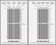
This should be just fine if you use Configuration 2 and make the first segment 0.75”. This satisfies the other recommendation to keep the first segment < 17mm wide. As golfnut mentioned, you will need to use a lower resistance value for the first segment of R/4.3) The with the number of segments at 10, the size is 1.5 inches wide. Too wide?
The resulting configuration will be a center segment of 0.75” width. The second segment is 1.5” wide, but will be split into two halves putting 0.75” to the left of the center segment, and 0.75” to the right of the center segment. Repeat for the remaining 8 segments. Total width = 14.25”
If you tell me what fL you plan to use, I can post the polar response.
If you position subwoofers in close proximity to your ESLs, it is a possibility depending how low the diaphragm resonance frequency is. You can experiment with placement while the sub is playing bass heavy music, but the ESL is un-driven and bias supply off.4) These ESL's will be used in a home theater room and as such I have a big subwoofer (that I built). Any danger of the SPL of that sticking the diaphragm to the stators? What happens when/if that happens (fires etc...)?
What happens depends on your stator insulation and conductivity of your diaphragm coating. With Licron coating and PVC insulated wires typically nothing happens other than the slapping noise and slight/temporary loss of sensitivity. If diaphragm is metalized and stators un-insulated, you will get arcing and flames.
Attachments
Last edited:
Thanks Bolserst!
I totally get the capacitance thing now. I was thinking the capacitance of the wire, not the entire segment setup.
BTW, I was thinking about going with 12 segments... for no other reason than to spread out the power dissipation of the resistors.
Probably the X-over will be around 250hz. Given my d/S spacing and expected resonance, I probably shouldn't risk anything lower. I am open to suggestions here though. And I would love to see the polar dispersion patterns!
Also, is there anyway to calculate/estimate the sensitivity of this panel? Just thinking ahead to designing the "woofer box". Which I am kicking around a dipole woofer idea with a woofer on the front/back aligned just like the ESL panel..... not sure if it is a good idea or not yet") .
.
Thanks so much!
I totally get the capacitance thing now. I was thinking the capacitance of the wire, not the entire segment setup.
BTW, I was thinking about going with 12 segments... for no other reason than to spread out the power dissipation of the resistors.
Probably the X-over will be around 250hz. Given my d/S spacing and expected resonance, I probably shouldn't risk anything lower. I am open to suggestions here though. And I would love to see the polar dispersion patterns!
Also, is there anyway to calculate/estimate the sensitivity of this panel? Just thinking ahead to designing the "woofer box". Which I am kicking around a dipole woofer idea with a woofer on the front/back aligned just like the ESL panel..... not sure if it is a good idea or not yet
. Thanks so much!
Last edited:
Hijeronimo83
A number of useful points….
First, I would not do exactly the same thing again.I removed all of the low voltage windings from the toroids, and then rewound them (in the sausage form) with a single winding.I was hoping to get the leakage inductance down, but in fact it made so little difference I should never have bothered. They can just be stacked together as supplied.
Second, you need to get your head around the voltage rating of the transformers.Let’s consider a single winding – say a 6V winding on 50 Hz transformer, for the moment. This will have been designed to just avoid saturating the core at 6V rms and 50 Hz.If you raise the frequency then the voltage rating of the winding will increase proportionally.So a 6V/50Hz winding will handle 30Vrms at 250 Hz.The 230 V winding will then produce up to 5x230V =1150Vrms on the high voltage side.
Therefore, for hybrid ESL with a relatively high crossover frequency, you do not need a lot of transformers. If the core saturates at the peaks of waveforms, it will present a transient short circuit to your power amplifier accompanied by lots of distortion. It’s a good idea to make sure the primary circuit has resistance of an ohm or so to prevent the current from racing before your amplifier blows up in an effort to protect the fuse. J
If you are operating with a crossover (not a full-range ESL) you should also make sure that the transformers are placed after any crossover (active or passive) so that no low frequency content gets to the primary winding.
Thirdly, most mains rated power transformers are manufactured to an IEC standard that requires them to have sufficient insulation between the primary and secondary windings to withstand 4kV dc for a minute (perhaps 2 minutes?). So there is usually no high-voltage breakdown risk between the primary and secondary windings.There is however a risk of breakdown where the two ends of the high voltage winding meet on the toroid, so I would err on the side of safety and use at least four transformers per ESL.Perhaps someone can provide advice on the voltage rating of enamelled transformer wire?
OK – so figure out what low-voltage rating the transformers should have – lets say you need 36V ac at 200 Hz.This would correspond to 9Vac at 50 Hz – so chose power transformers with a 9V secondary.Each transformer gives you a step up ratio of 230/9=25.So you could achieve an overall step up ratio of 150 by using 6 transformers – 3 on each side of the HT.Hook all of the 9V windings in parallel, and all of the 230V windings in series.
I did a lot of experiments on some Talema transformers in the 15P1-XXX series (see http://www.nuvotem.com/en/products/std_open230v.shtml). These are small 15VA transformers with a single 230V winding, they occasionally turn up on discount at radio spares at about US$10 -$15 ea. (There must be others making similar transformers too). I found the leakage inductance is 16 mH and capacitance is about 100 pF(unloaded resonant frequency of 126 kHz).When the secondaries are connected in series, the leakage inductances add (=96 mH). The capacitance model is not as simple, some parts add in series, and some parts of the capacitance add in parallel. I can’t remember the figures at the moment, but even with 16 transformers, the resonant frequency was above 40 kHz – so heaps wide enough for an ESL.
Finally, don’t waste money on the transformers with the twin 110 V windings – the windings are usually laid down on the core simultaneously – two wires side by side, so the capacitance is huge, and the risk of breakdown is greater. They are no good for ESLs.
regards
Rod
golfnut:
Any recommendations for transformers that I can get my hands on on this side of the pond?
I can't seem to find single wound 230V toroidals anywhere. I heard some places (antek maybe?) will build you a transformer if you provide the specs.... what would the "ideal" ESL transformers for a hybrid ESL look like?
golfnut:
Any recommendations for transformers that I can get my hands on on this side of the pond?
I can't seem to find single wound 230V toroidals anywhere. I heard some places (antek maybe?) will build you a transformer if you provide the specs.... what would the "ideal" ESL transformers for a hybrid ESL look like?
You're wasting your time looking for them in the US. Rapid Online in the UK has toroids with a single 230V winding HERE and they will accept a US credit card and ship to the US.
I would love to see pics of that rig. I've been thinking thru ideas myself for a setup that will allow me to make those stator panels quicker.
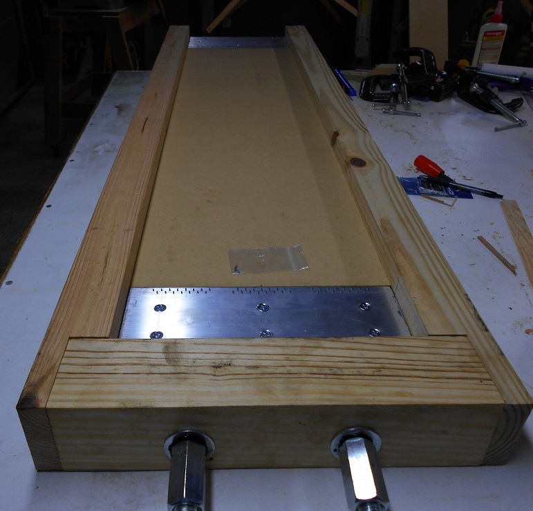
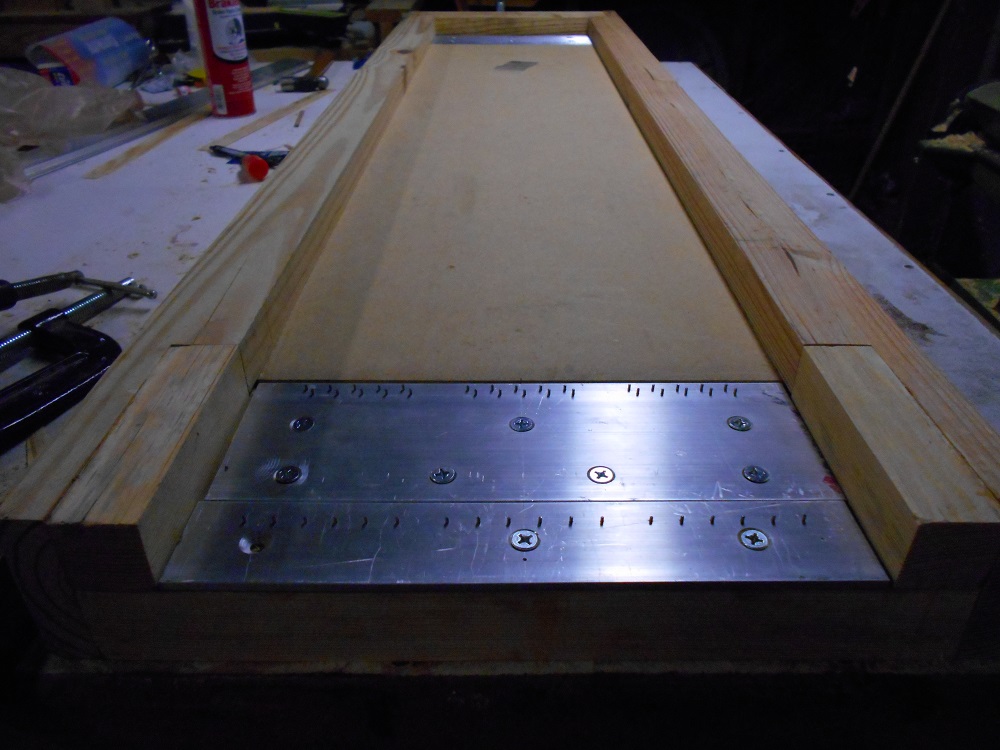
I finished my wire stretching jig today. As I noted earlier, it functions backwards insofar as it stretches the wires over a flat surface and the stator is then laid down (or assembled) over the stretched wires as opposed to stretching wires over a pre-assembled stator. My preliminary stretch test showed that I only need to stretch the wires about 1/2 inch so I gave the jig only 3/4" travel and it's specifically designed for 12 x 48 inch stators.
I can't say how well it will work but here it is:
Last edited:
Yeah, the TIG rods arrived in the mail today... I can see it is going to take awhile to build the stators
It won't be so much work if you don't solder/splice the rods to get the length you want (I did but I wouldn't again).
Let's say you want the panel to be 46" tall and you are using 36" rods. In this case you could merely cut and butt the rods at one of your horizontal spacer locations. The downside to not solder/splicing the rods is that you then have to run your connections to both ends of the rod groups.
well.... the issue is, I am using the parahex support grid which doesn't offer straight lines across. So I am thinking I might have committed myself to splicing the rods together.
Still waiting on the parahex stuff so I will tinker around with it and see what I can come up with.
I will post polar patterns for a few segmentation options tomorrow.I was thinking about going with 12 segments... for no other reason than to spread out the power dissipation of the resistors… I am open to suggestions here though. And I would love to see the polar dispersion patterns!
I’m not sure power dissipation of resistors will changed much going from 10 to 12 segments. You may recall that it is mainly the first few segmentation resistors that have the large power and voltage requirements. As an example, see Post #103 for power/voltage requirements for CharlieM’s previous build.
You would need to know the transformer step-up ratio.Also, is there anyway to calculate/estimate the sensitivity of this panel?
The spreadsheet currently only shows maximum possible SPL.
An input for transformer ratio could be added and another curve shown for Vin= 2.83Vrms.
I’ll see about updating it with that option and posting it later this week.
In the mean time you could:
1) manually enter a peak stator voltage into the current spreadsheet = 2.83Vrms * (step-up ratio)*(1.414)
2) use the “esl_seg_ui” calculator
Nice looking jigI finished my wire stretching jig today.
It's hard to tell from the pics, but one area of concern is the possibility of the end blocks pivoting due to the wire tension being in a plane above the reaction points of the threaded rods. This could generate a lot of friction at the contact points between the end blocks and the upper and lower surfaces of the wooden slots. I was able to deal with this in my stretcher with grease on the sliding metal surfaces, not sure how it will work out with wood. you could always add some steel shim stock at the contact points if needed.
I hope your rods don't have certification stamps at each end, I had to bundle them with hose clamps and saw them off in cut off saw, and then clean up the tips. Left them 32" long.
Al
Mine are shiny clean and straight but I have the small rods (.03X).
Nice looking jig
It's hard to tell from the pics, but one area of concern is the possibility of the end blocks pivoting due to the wire tension being in a plane above the reaction points of the threaded rods. This could generate a lot of friction at the contact points between the end blocks and the upper and lower surfaces of the wooden slots. I was able to deal with this in my stretcher with grease on the sliding metal surfaces, not sure how it will work out with wood. you could always add some steel shim stock at the contact points if needed.
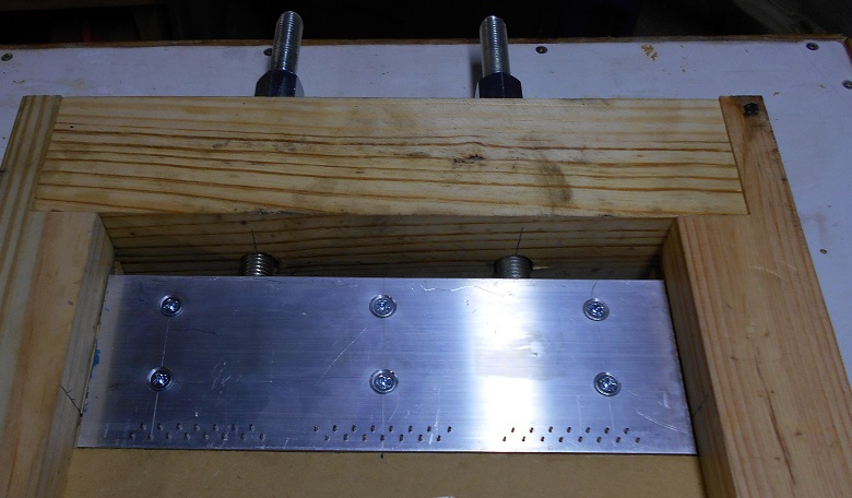
Good idea... I could add some steel shim stock (feeler gauge blades) in the slots the steel plate rides in. You cant see the steel plate in the photos but the aluminum plate on the pulling end bolts to a 1/4" steel plate that's welded to the jack screws (3/4 all-thread rods).
I ground flats on the jack screws (1/3 of their diameter) where they weld to the plate to help minimize the offset between the wire axis and jack screw axis.
I have the pins angled 4 degrees back to keep the wires on the pins. BTW, I had to use larger pins (.0625" dia.) because the size pins that would give the correct wire spacing (1mm dia.) bent over when I tested them. So, I will have to use threaded rods to set the wire spacing after I pull the wire and relax the tension a bit.
Last edited:
Thanks bolserst and Golfnut for your detailed explanations.
Charlie, that stretching jig is looking very sleek. Be sure to wear safety goggles though, must be a lot of force in there when stretching. I had a rather thick insulated wire break down on me when trying to stretch it by rotating the wire, and it scared the sh*t out of me. Different method , I know, but I think similar forces.
Charlie, that stretching jig is looking very sleek. Be sure to wear safety goggles though, must be a lot of force in there when stretching. I had a rather thick insulated wire break down on me when trying to stretch it by rotating the wire, and it scared the sh*t out of me. Different method , I know, but I think similar forces.
Nice looking jig
It's hard to tell from the pics, but one area of concern is the possibility of the end blocks pivoting due to the wire tension being in a plane above the reaction points of the threaded rods. This could generate a lot of friction at the contact points between the end blocks and the upper and lower surfaces of the wooden slots. I was able to deal with this in my stretcher with grease on the sliding metal surfaces, not sure how it will work out with wood. you could always add some steel shim stock at the contact points if needed.
well bolsert returns
long time not seen.Btw i have used a lineair rail under the plate with the nails on the side you tension them so it wont pivot, since i noticed the same problem, the thing will pivot and wires may come lose or it will have so much friction it is almost impossible to stretch any further. mine where pretty overkil even for a big cnc machine
but i thought i bought minatures. but they where 2 kilo's each for only 20 cm of track hahanice thing though is the screw you tention with never bends or get added friction on the thread. hell you could even use 1 screw in the middle since the load such bearing can handle is pretty high
Last edited:
Thanks bolserst and Golfnut for your detailed explanations.
Charlie, that stretching jig is looking very sleek. Be sure to wear safety goggles though, must be a lot of force in there when stretching. I had a rather thick insulated wire break down on me when trying to stretch it by rotating the wire, and it scared the sh*t out of me. Different method , I know, but I think similar forces.
the difference is one wire or 40x 1.5mm2 wires .... thats allot of force.
Yikes! When you say bent over, do you mean deflected by force but would return to straight when force was removed? or permanently deformed. I was surprised to to read this since with the wires snugged down to the surface of the aluminum plate, the pins should be loaded in shear with very little bending moment applied. Also, most dowel pins are hardened steel and like drill bits will snap rather than bend.... I had to use larger pins (.0625" dia.) because the size pins that would give the correct wire spacing (1mm dia.) bent over when I tested them.
BTW, what insulation thickness and wire spacing did you decided on?
According to Roger Sanders, inventor of the curved ESL, the performance of curved panels is compromised in favor of polar response. Part of one of his descriptions (not the one below) explained that the diaphragm sags inward between the curved ribs, raising distortion and energy storage. Compared to flat panels, such as Quad's ESL-57 ESL-63, curved panels like the ML CLS exhibited poorer settling characteristics.With ESL's if we look at well established manufacturers like Martin Logan
and Quad ,they all curve the panel area.
Listening to ESL's that lack curving is very difficult and almost ridiculous.
You end up with extreme beaming, but with a curved panel excellent reproduction.
You should try to hear Quad ESL's and Martin Logans, to ascertain how
curving the panel is an essential requirement.
http://www.quadesl.com/pdf/quad_book.pdf
and a great video showing what is involved with
building them at Martin Logan https://www.youtube.com/user/MartinLoganSpeakers
Cheers / Chris
the panel
"A major part of his work was devoted to dealing with the issue of high frequency "beaming" in large, planar loudspeakers.* To deal with this issue, he invented the free-standing, curved, electrostatic panel.* This made it possible to widely-disperse the high frequencies from a large*ESL.* He published this invention in Speaker Builder Magazine in 1980.* The Martin Logan company adopted his technique in their*ESLs.
Roger expected that his wide-dispersion, curved panels would perform better than narrow-dispersion, planar speakers. But he discovered that the curved panel was inferior to a planer one with respect to transient response, imaging, frequency response, speaker placement, and output.****These problems caused by wide-dispersion speakers spraying their sound all over the room instead of being directed at the listener.* As a result, in a wide-dispersion speaker, the listener hears the room with all its confused and delayed reflections instead of the superb sound available directly from a planar*ESL.** Roger won't compromise the quality of the sound by using his wide-dispersion design, so he abandoned it in favor of planar*ESLs.* The sound from his planar speakers are superior to all others with regard to transient response, 3-dimensional imaging, and frequency response." -Except from Roger Sanders, at Sanders Sound Systems - Electrostatic Speakers
- Status
- This old topic is closed. If you want to reopen this topic, contact a moderator using the "Report Post" button.
- Home
- Loudspeakers
- Planars & Exotics
- About to take the ESL plunge