Here is the site: Electrostatic Loudspeaker (ESL) Simulator
I'm not sure what to plug in for the values. How would I know what to put in for
1) drive voltage
2) series resistance
3) leakage inductance
4) constant current drive
I would like to simulate a esl driven by a Acoustat MK121 (with all the updates)
When you open up the program it has 6000V for the drive voltage. I guess this is the several volts from the amplifier multiplied via transformer in the MK121 to ~6000V?
Thanks for your help
Paul
Hi!!
Drive voltage is the simply your drive voltage (RMS I believe) being applied to the panel stators.
Series resistance is any resistance that you may have in series with the Stators.
This does two things,
It is a form of current drive, and, it help dampens any peaks caused be the transformers leakage inductance.
The calculator is setup so that the resistance values are being added on the HV side instead of traditionally into the low voltage side.
If you want to use the LV method you simply multiply your added resistance by the turns ratio squared and enter that into the field.
Or LVohms * Ratio^2=HVohms .
Leakage inductance is a value that pertains to your transformer and it is either in its data sheet or must be found manually, Refer to the thread on "ESL step up transformer design" for more info here,
http://www.diyaudio.com/forums/planars-exotics/161485-step-up-transformer-design.html#post2094251
It is shown this thread how to test your transformer to determine such parameters including Transformer Ratio and Capacitance and how this effects the frequency response.
Constant current drive is the same effect as having a resistor is series with the stator's and is set by the current driving the stators, it has its own graph line in yellow.
One note is that if you add anymore series resistance this changes this graph line as well.
This page also explains how the calculator model works as well,
ESL simulator - technical background on Walker's equation
I hope this helps you.")
jer
Drive voltage is the simply your drive voltage (RMS I believe) being applied to the panel stators.
Series resistance is any resistance that you may have in series with the Stators.
This does two things,
It is a form of current drive, and, it help dampens any peaks caused be the transformers leakage inductance.
The calculator is setup so that the resistance values are being added on the HV side instead of traditionally into the low voltage side.
If you want to use the LV method you simply multiply your added resistance by the turns ratio squared and enter that into the field.
Or LVohms * Ratio^2=HVohms .
Leakage inductance is a value that pertains to your transformer and it is either in its data sheet or must be found manually, Refer to the thread on "ESL step up transformer design" for more info here,
http://www.diyaudio.com/forums/planars-exotics/161485-step-up-transformer-design.html#post2094251
It is shown this thread how to test your transformer to determine such parameters including Transformer Ratio and Capacitance and how this effects the frequency response.
Constant current drive is the same effect as having a resistor is series with the stator's and is set by the current driving the stators, it has its own graph line in yellow.
One note is that if you add anymore series resistance this changes this graph line as well.
This page also explains how the calculator model works as well,
ESL simulator - technical background on Walker's equation
I hope this helps you.
jer
Here is the site: Electrostatic Loudspeaker (ESL) SimulatorI'm not sure what to plug in for the values….I would like to simulate a esl driven by a Acoustat MK121
The short answer is that you can’t use this simulator to directly model an ESL driven by the Acoustat MK-121 interface because it includes crossover parts and 2 transformers. But, you can use the simulator to help get the acoustic response of the panel to combine with the electrical response of the interface.
You need to be aware of the limitations of the calculator. It assumes a flat, rectangular, un-segmented, uniformly driven panel. It does not account for diaphragm mass or resonance modes, baffle extensions, or room interaction. It does not check to see if voltage levels will cause arcing, or diaphragm hitting the stator. Even with those limitations, it is useful for sanity checks on SPL levels, and response trends for panel shape/dimensions or listener distance/position. Works great on my cell phone
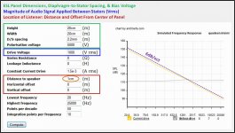
Below are a few example results working toward modeling the Acoustat response.
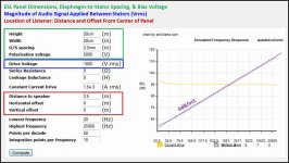
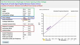
Attachment #1:
This shows the predicted response @ 2.5m for an 8”x8” ESL panel. Note that the response slopes up at 6dB/oct if driven by constant voltage, and flat if driven by constant current. As geraldfryjr mentioned, the drive voltage is the voltage between the stators which = (amplifier voltage) x (step-up ratio).
More info here on the 6dB/oct slope of point source ESLs:
http://www.diyaudio.com/forums/plan...se-cancellation-esl-speakers.html#post2856955
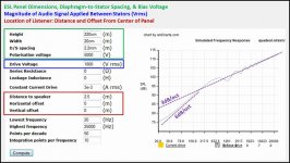
Attachment #2:
If we increase the height of the ESL to model an Acoustat sized line source, you can see that the slope of the response changes to 3dB/oct over most of the audio band. At the lower frequencies, the response reverts to the 6dB/oct slope of a point source. Note that the transition frequency increases as you move further from the ESL. If the line source was placed in a room and extended from floor to ceiling the slope transition would not take place.
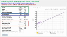
Attachment #3:
If we move the listener off axis a bit (~4.5deg) you can see that the HF response rolls off dramatically(-3.5dB@10kHz, -15dB@20Khz). This is because of the beaming(high directivity) behavior of a large flat panel. Acoustat listeners are no doubt familiar with how the highs change with a small shift in panel or listener position.
Off Axis Angle = arctan( Horizontal offset / Distance to speaker )
Attachment #4:
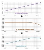
The take away from the previous examples is that the on-axis acoustic response of a line source like the Acoustat is essentially that of a +3dB/oct slope. If we account for the relatively thick diaphragm it uses(17µm), we will have a much better representation of its acoustic response. The HF roll off from the diaphragm mass actually provide a fairly flat response from 2kHz to 10Khz.
More details on accounting for diaphragm mass here:
http://www.diyaudio.com/forums/plan...tatic-speakers-microphones-5.html#post3427260
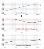
Attachment #5:
If a SPICE model is used to calculate the electrical response of the Acoustat MK-121 interface we can combine it with the panel acoustic response to get the overall electro-acoustic response. Note that the Acoustat interface uses two transformers to provide shelving compensation to equalize that naturally falling response of ESL dipole line source. It also uses the underdamped LP filter formed between the HF transformer leakage inductance and panel capacitance to boost the top octave response. The MK-121 interface includeds an adjustment to the damping resistance to tweak the amount of top octave boost for listener preference.
More details on the MK-121 interface response here:
http://www.diyaudio.com/forums/plan...cls-ii-stators-best-way-do-2.html#post3822064
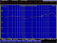
Attachment #6:
Here is an overlay of the modeling response with an on-axis measurement I took a few years back. The overall trend looks to be on target. The dip just above 1khz and boost below 800Hz are most likely a result of the frame surrounding the panels effectively providing a small baffle extension around the panel. You could use a baffle diffraction simulator like "the EDGE" to approximate the baffle effect if desired.
Attachments
-
 ESL_Pointmodel_on-axis.jpg90.1 KB · Views: 359
 -
 ESL_Linemodel_on-axis.jpg90.6 KB · Views: 350
 -
 ESL_Linemodel_5deg_off-axis.jpg90.6 KB · Views: 353
 -
 Acoustat_Response_Model_01.jpg80.7 KB · Views: 355
 -
 Acoustat_Response_Model_02.jpg83.1 KB · Views: 349
 -
 Acoustat_Response_Model_03.gif73.6 KB · Views: 139
Last edited:
A resistor forms a constant current Source as it's value is constant compared to the changing impedance of the panels capacitance with frequency.
Providing that the panels reactance (impedance) is lower than that of the resistor, the current remains constant through the resistor and never goes above a set value by the resistor and driving voltage.
Therefore the voltage drop changes across either the resistor and/or the panel with frequency.
I hope I said that right !!
jer
P.S. Maybe this will help,
http://www.learningaboutelectronics.com/Articles/What-is-a-constant-current-source.php
http://www.learningaboutelectronics.com/Articles/Ideal-current-source.php
https://www.youtube.com/watch?v=AsBx52mWzwM#t=94
https://www.youtube.com/watch?v=RYz...re=iv&annotation_id=annotation_642229767#t=5s
Last edited:
when they speak of constant current or constant voltage, where is the quantity constant? Is it the diaphragm or stators to which they are referring?
The drive voltage and constant current referred to in the esl simulator are the voltage applied across the stators, or the current through the stator to stator capacitance. Essentially all amplifiers available for audio use are constant voltage types rather than constant current. But, as geraldfryjr mentioned, you can emulate a current source if a high value resistance is put in series with the voltage source.
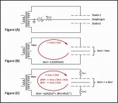
Take a look at the figures in Attachment#1.
Figure (A) shows the typical transformer driven ESL configuration.
Figure (B) shows that for this circuit, the voltage from the step-up transformer (Vsec) is applied directly to the ESL stators. This would be constant voltage drive. The current through the stator circuit = Vsec / Zesl. The ESL impedance(Zesl) is that of a capacitor that falls with increasing frequency; halving ever octave increase. So, the current doubles ever octave increase.
Figure (C) shows how inserting large resistances in series with the stator capacitance can approximate constant current drive at higher frequencies. Basically as frequency increases the ESL impedance(Zesl) starts to look like a short circuit. So, at higher frequencies the current will be constant and defined solely by the series resistances Rs1 & Rs2. At lower frequencies, Zesl becomes much larger than Rs1,2 and the behavior transitions to that of constant voltage drive.
Note that in a properly operating constant charge ESL, little or no current flows in the diaphragm or HV bias supply circuit once the diaphragm has been fully charged.
Attachment #2: The point source ESL simulation from post #3 has a stator-to-stator capacitance of about 80pF. If we insert 3.7Mohm resistance in series with the stators we see that the response flattens out above 1kHz where the current becomes constant and defined only by this series resistance. At lower frequencies, the 6dB/oct slope of a voltage driven point source remains.
Attachment #3: One other interesting thing you can investigate with the esl simulator is what happens when your ear gets really close to the ESL diaphragm; like with ESL headphones. Note that the near field response is quite different from the far field response shown post #3. In the near field constant voltage drive results in a flat response while constant current drive results in a response sloping down at 6dB/oct.
Attachments
Last edited:
- Status
- This old topic is closed. If you want to reopen this topic, contact a moderator using the "Report Post" button.
- Home
- Loudspeakers
- Planars & Exotics
- Help with esl simulator