That is a method that I would not suggest to use if you value your meter.
Also just because the meters spec sheet may indicate it's input resistance or impedance is X, you have no proof of exactly what value it really is, it is just a generalization and it could be off by as much as 5 or 10 percent if not more.
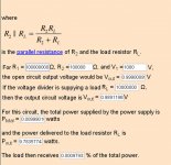
In this example for a voltage divider total of 100meg (actually 100.1meg) and a bottom resistor of 100K, A meter with a 10Meg input resistance shows error of only 1% due to the loading of the meter across the bottom 100K resistor.
Voltage Divider
This is not bad and much safer for your meter at 1V per 1000V displayed.
I use a 10k or 20k multi-turn trimmer pot included on the bottom as well to calibrate it to more exact scale as well.
You can probably also get away with skipping the opamp buffer if your meter that has that high of an input impedance.
The nice thing is that some opamp's have an input resistance has high a 1Gohm and higher, Some do not you must check for this in the spec sheet of the opamp you may be trying to use.
Mine are not that high at about 200k to 2 meg for my DMM's.
For an analog meter you will need to use a buffer to keep it accurate or use a trimmer to calibrate it, most are typically 20k or less.
The calculator above is a great tool for finding the right values of resistance to use.
In this example Ptotal is .00999 watts and 9.7835e-08 watts to the RLoad so don't be alarmed by the value in the screenshot.
Cheers!!
jer")
Also just because the meters spec sheet may indicate it's input resistance or impedance is X, you have no proof of exactly what value it really is, it is just a generalization and it could be off by as much as 5 or 10 percent if not more.
In this example for a voltage divider total of 100meg (actually 100.1meg) and a bottom resistor of 100K, A meter with a 10Meg input resistance shows error of only 1% due to the loading of the meter across the bottom 100K resistor.
Voltage Divider
This is not bad and much safer for your meter at 1V per 1000V displayed.
I use a 10k or 20k multi-turn trimmer pot included on the bottom as well to calibrate it to more exact scale as well.
You can probably also get away with skipping the opamp buffer if your meter that has that high of an input impedance.
The nice thing is that some opamp's have an input resistance has high a 1Gohm and higher, Some do not you must check for this in the spec sheet of the opamp you may be trying to use.
Mine are not that high at about 200k to 2 meg for my DMM's.
For an analog meter you will need to use a buffer to keep it accurate or use a trimmer to calibrate it, most are typically 20k or less.
The calculator above is a great tool for finding the right values of resistance to use.
In this example Ptotal is .00999 watts and 9.7835e-08 watts to the RLoad so don't be alarmed by the value in the screenshot.
Cheers!!
jer
Attachments
Last edited:
Using a 10M for the final grounding resistor keeps the testing point voltage low.
It also allows easy calculation for the loading effect of the 10M meter probe.
45M +10M gives an effective 45M +5M for a 10:1 reduction using the 10M meter. But more suitable for measurements < 2kV
Alternatively you could use 1M1 for the lowest resistor.
Then 99M + 1M1 gives an effective 99M + 1M for a 100:1 reduction using a 10M meter.
Are these resistive dividers just as effective with AC and DC?
The lower you make your Bottom grounded resistor the lower your testing voltage is of course but also the lower it is compared to the input resistance of your meter the lesser percentage amount of error you will have from the loading of RL(aka Meter)
If you have a a 10meg for the bottom resistor and your meter as a 10meg input resistance(or impedance) then your bottom resistor is now effectively 5meg and this will give you half of the voltage reading that you would be expecting.
The ratio of the bottom resistor and your meters input resistance will give what margin of error to expect as follows (Bottom resistance/Meter resistance)*100=margin of error in %.
In the above example (100,000 ohms /10,000,000 ohms)*100= 1% error as shown by the calculator in the screenshot.
If your bottom resistor was 10k then your margin of error would only be .1% with the same meter, and for 1Kv this would only be 10v of error per 1Kv .
FWIW
jer
Last edited:
No and No.The lower you make your Bottom grounded resistor the lower your testing voltage is of course but also the lower it is compared to the input resistance of your meter the lesser percentage amount of error you will have from the loading of RL(aka Meter)
If you have a a 10meg for the bottom resistor and your meter as a 10meg input resistance(or impedance) then your bottom resistor is now effectively 5meg and this will give you half of the voltage reading that you would be expecting..............
You must know your loading effect on the circuit being tested.
You calculate the effect of the loading.
I gave two alternatives that use the known loading effect.
Then showed what the results are. There is virtually no "error".
Using the 10M lower resistor parallel to the 10M meter, gives an effective 5M for the lower resistor.
There is no 50% error.
If the 10M resistor is +-1% and the meter impedance is +-5% then the combination is 5M +-2.96%
Use that with 45M +-1% for the upper resistor string and the divide ratio is 10:1 +-<4%
And with selection of the resistors using a couple of DMM that can measure 5M & 10M resistors, by comparison, you can get a divide by 10 ratio much closer to +-0.5%.
Then use your Hamon divider in a Wheatstone Bridge to check how good your ratio has turned out to be. With care you can get <<1% and maybe approach 0.01%
You are left with the meter accuracy as the only significant error in the measurement result.
Last edited:
Yes, you are correct Andrew I didn't read or post properly, as have been up all night now working on learning some C.
I do apologize for my mistake.
I got to thinking about my example and I used a generalization and I do like to be exact.
Leaving out the ratio of the top resistor makes a big difference as well as not using the proper formula for the parallel resistance for the bottom two combined resistances.
It is late for me and I thank you for pointing that out for me.
Sorry for the confusion.
My math is good but I forget to think out complete formula's now and then, mostly from laziness of having to try and type them out and make them look right and understandable in the forum.
But it is no excuse for my sloppiness and is why I rely on online calculators anymore. He,he,he!!
Cheers !!!
jer
I do apologize for my mistake.
I got to thinking about my example and I used a generalization and I do like to be exact.
Leaving out the ratio of the top resistor makes a big difference as well as not using the proper formula for the parallel resistance for the bottom two combined resistances.
It is late for me and I thank you for pointing that out for me.
Sorry for the confusion.
My math is good but I forget to think out complete formula's now and then, mostly from laziness of having to try and type them out and make them look right and understandable in the forum.
But it is no excuse for my sloppiness and is why I rely on online calculators anymore.
He,he,he!!Cheers !!!
jer
Last edited:
I exercise my brain by thinking through in my head and coming up with a very approximate estimate of what to expect, if and when I need to write it out and use a calculator.
I am not much into computer modeling, unless I can check it is reliable AND understand what it is doing to arrive at a prediction.
Does anyone want to comment on
I am not much into computer modeling, unless I can check it is reliable AND understand what it is doing to arrive at a prediction.
Does anyone want to comment on
Are these resistive dividers just as effective with AC and DC?
In my experience, a resistive divider should behave exactly the same with AC or DC until the AC frequency increases to the point where the parasitic L & C components start to have significant effect on the equation. A "practical" resistor can be modeled as a purely resistive element in series with an inductor with a parallel capacitor across the series network.
The lower limit of usable resistance is affected by parasitic inductance. For leaded resistors, this results in a lower limit of ~10 Ohms at 100 MHz. At 50kHz, this won't be much of a factor at all (<0.0004 Ohms with 1nH).
The upper limit of usable resistance is affected by parasitic capacitance. At 50 kHz (the approx frequency of the supply), the Xc will be ~3.2M at 1pfd. Using SMT components will yield lower parasitic capacitance than with leaded components, but also lower breakdown voltages.
Last edited:
I am not much into computer modeling, unless I can check it is reliable AND understand what it is doing to arrive at a prediction.
If you dared offer that intelligent advice on any of the other loudspeaker forums, they'd be out looking for you with knives.
Pity.
Ben
A simple computer simulation of the LF of a driver can be compared to doing it longhand and to some publication like "Bullock on Boxes".
That builds both trust in reliability of the predictions and an understanding since the results can be arrived at using fairly simple but quite extensive calculation.
A simple speaker box simulation meets BOTH requirements. I am happy with that.
Anyone that blindly accepts a computer prediction without first checking the reliability and accuracy is irresponsible.
Last edited:
Anyone that blindly accepts a computer prediction without first checking the reliability and accuracy is irresponsible.
Off-topic but brief...
even if the model's math is assumed to be trustworthy, you forgot to mention a model consumer also must understand and agree with the assumptions and various premises of the model. How often is that the case for amateur consumers?*
B.
*Anybody want to tell me what's uniquely desirable about a box with a Q=.7?
Yes, there is ripple, even more so using such small value of capacitors in the multiplier at low frequency's such as 50/60hz.
This of course has a lot to do with the current flowing in the circuit as well.
In this post there are some Photos of the ripple voltage from my regulated HV supply,
http://www.diyaudio.com/forums/plan...tor-insulation-mylar-coating.html#post2782115
The supply runs at about 180Khz to 210Khz and this ripple can easily be filtered out some more.
I have not taken the time to measure the ripple voltage of the common 60Hz DIY supply yet.
I will be able to do this later in the summer after I retrieve Mavric's DIYed ESL's from Georgia.
I will do a complete rundown and performance test on his system when I get them for all to know what to expect from such a build.
jer
Hi Guys, hope this is the right place to ask.
Need help to find a suitable transformer.
I tried my luck with this design :
http://www.quadesl.com/speaker/diyesl/hv_supply.pdf
Now I need some transformer like that 1.1 VA 6.3 V Microtran by Tamura any way one that can be directly driven by the IC555 in 15 kHz.
I am not sure what transformer specs will do the job and cannot find specs transformer specs with 15kHz.
This might help you.
PREM Transformer SPW-1001 Dual 115/230V Primary 2.5VA Series 12.6VCT @ 200mA Parallel 6.3V @ 400mA
As long as your drive frequency is 60Hz or above there are no issues.
it was that very circuit that inspired me to design the supply I made, driving with just a single 555 just didn't supply enough current for me, using my leaky panels at the time.
jer
Last edited:
Thanks for the amazing quick reply.
Are you sure those will work? I tried very similar ones that do not work, the 15kHz is very likely the the problem, I specifically wanted the higher frequency apart from the possibility to be able to adjust/optimize the voltage because my first 50Hz attempt failed in the voltage multiplier part.
I guess bigger capacitors must be used then, I tried 10 nanoF as in several examples found here.
BTW a store in Europe would be nice too
The IC555 can drive 200mA max, but it delivers about 0 mA at 15kHz with this one :
Vigortronix VTX-126-006-606 Chassis Mains Transformer 6VA 2x 0-6V | Rapid Online
And just now I found out I ordered a 6VA instead of a much smaller one :-(
I don’t know what characteristics are important for the higher frequency but I suppose a very low power transformer will do better than a bigger one.
Can you confirm that?
I can't tell you for sure if that part will work or not without actually knowing all of it parameters, it should.
But as I mentioned I built that supply and found it to be inadequate for my DIY panels as they were quite leaky at the time.
The 555 may very well be rated for a 200ma drive current but that doesn't mean that is what you are driving the winding with.
Going up in Frequency is usually a good thing normally, not knowing the transformers parameters may or may not be an issue here, most likely I am guessing other factors are involved as well.
Using a proper driver output stage is the main thing I have found with this circuit.
See this post and read through the whole thread you may find it useful,
how can test the stator insulation and mylar coating?
As mentioned in the thread I discovered that only the True Bipolar versions of the 555 such as the ones from TI were the only ones that I could get to work in my design.
All of the CMOS versions that I tried failed in driving power and I went through a few driving such high currents from those 555's.
None of the CMOS versions I used would work at the +180Khz that I needed and was pushing them to also would not work either.
When feeding your multiplier stage with a higher frequency you are able to have a faster recovery time, should the stack discharge.
And you will get more current available from the stack as well because of it, compared to feeding it with a 60Hz signal.
Try using a larger value cap from the 555 feeding the winding as well, this will reduce the impedance to the driving signal as well and allow you a bit more current to drive the winding with.
The main problem I found was that if do not have a proper amount of driving current and not a low enough impedance to ground while the 555 is at a low state then the electrons pyle up and start to form a Floating DC voltage above some frequency in the 1Khz to 5khz range and higher. (YMMV) .
This is not good for the winding as the DC Voltage causes a current that is saturating the transformers core rendering a much lower result on the output winding.
I found this to be especially true by directly driving my FET's right from the 555 as well and my FET's were getting hot because they were being biased on all the time in their linear range due to that floating voltage and not completely switching off to dump the current to ground.
Adding the the PNP & NPN BJT output buffer solved all of those issues for me and I was able to directly drive my FET's before and after using a Gate Transformer just fine after that.
I started with just one single FET but later switched to using two of them in a simple Class B configuration for more power output for my applications.
Hope this helps you.
jer
P.S. One more issue is that make sure that you are using some Fast Recovery Diodes as well, We had a small discussion about that in the thread and the ones I used worked, but marginally at that and because of their slow switching renders my performance a bit less than what it could be, although it does work just fine for my needs right now I can still pull a continuous arc at 10-12Kv with about 40 watts of power full at blast.
In newer versions I will use the properly rated Fast Recovery diodes as specified.
Last edited:
You have seen this: LT3751 Datasheet and Product Info | Analog Devices
They also offer a development board for $125.
They also offer a development board for $125.
Just got an email recently from Coil Craft offering transformers for that chip !!
Made me take another look at it again, that was where I wanted to go with my design but the 555 was all I had to work with at the time.
Flyback Transformers for Linear Technology LT3751 | Coilcraft
jer
Made me take another look at it again, that was where I wanted to go with my design but the 555 was all I had to work with at the time.
Flyback Transformers for Linear Technology LT3751 | Coilcraft
jer
Patrick (EUVL) wrote it up here: LT3751 Driven, +/-400V Shunt Regulated Supply
- Status
- This old topic is closed. If you want to reopen this topic, contact a moderator using the "Report Post" button.
- Home
- Loudspeakers
- Planars & Exotics
- ESL High Voltage supply