Its long past time I shared my ESL experience with fellow DIYers here:
Background:
Many, many, years ago, before I was married, I had the pleasure of owning a set of Quad ESL-57s. Of course they were intolerable objects because they would not support potted plants. So under considerable duress I sold them and replaced them with KEF CS7s, the largest of the constructor series KEF made, which had ample room for potted plants.
Needless to say, I always regretted selling the 57s; stereo was never quite as addictive after that. years later, in late 2007, a work colleague asked me a silly question that prompted me to look into ESLs again. To my great surprise there was a good sized DIY community, and so I began …..
Acknowledgements:
In addition to the many people who post here, I owe special thanks to Rob McKinlay of ER Audio, whose notes on his ESL kitsets convinced me that a DIY project was feasible. Also, Rob introduced me to the Loudspeaker and Headphone Handbook (Borwick) chapter on ESLs by Baxandall, which was a revelation. I also owe thanks to colleague PM, whose encyclopaedic memory I pick, and MP for helping me when I get stuck on some basic acoustics theory. Finally, thanks to Bolserst for the many off-line discussions and advice.
The design:
Towards the end of Baxandall’s chapter he derives the ‘Walker Equation’ relating SPL to stator current, for a line source – actually a floor-to-ceiling doublet. The equation has an awkward sqrt(f) dependence, which superficially at least, looks hard to equalise. However, the input impedance of an RC transmission line also has a sqrt(f) dependence. That means that an ESL comprised of many segments of equal capacitance, each linked to its neighbour by a single resistor, will have a flat frequency response. Following some computer modelling, I discovered that the symmetric version of this ESL has some additional magic – a polar response that varies as a second-order Butterworth response versus angle – that means (i) a broad listening area near the on axis position, (ii) no zeros and phase reversals in the frequency response (causing the phasiness that wide-segment ESLs are known for) and (iii) a graceful decrease in treble as the listener moves of axis. The results of the study were published in JAES as “A wide range electrostatic loudspeaker with a zero free polar response”. Contact me if you want a pre-print.
Practical build:
There are unfortunately a few beginners’ mistakes – I’ll explain as I go.
The finished ESL is about 500 mm wide by 2320mm tall – designed to fit under a 2400 mm ceiling. According to the design equations, the ESL has a nominally flat response down to 80 Hz, and then falls a way as sqrt(f) below that. In practice diaphragm resonance will boost the low frequency end – see later. I have chosen the smallest segments to be 12 mm wide to ensure minimal diffraction effects from the finite segment width.
The stators are manufactured from eight sections of 1100 mm x 384 mm x 0.8 mm PCB with 3 mm wide slots. They are reinforced with acrylic ribs glued in between the slots, every 40 mm. The spacers are also acrylic, 3.0 mm. The final stator-diaphragm spacing is less than 3mm due to half a dozen coats of acrylic lacquer. I have used copper tape as the stator ring on the rear stator, 3.5 um Mylar (supplied by Rob McKinlay), and spray-on Licron (NZ supplier available). I used the technique recommended by Rob to attach the diaphragm – stretched on an old glass shower panel using duct tape, to constant tension, and glued using slow setting epoxy.
Mistake 1: I designed the mechanical construction, in particular the split down the middle of each panel, before I discovered that an asymmetric ESL has a terrible polar response. So on each panel, one half is symmetric transmission line (for treble) and the other (bass end of the transmission line) is asymmetric. Not too much damage done – within a couple of dB of ideal.
Mistake 2: I assembled the PCB stators with the copper surface inwards, and the machined edges (followed by sanding and etching to minimise the problems) mean that I begin to get corona discharges at about 4 kV, and I’m having to run the ESL with half of the polarising voltage that I hoped for – 2.6 kV. However, I find I have sufficient area to still get them comfortably loud. The HT supplies have 100 M ohm in series to ensure constant charge operation (minimise distortion).
Mistake 3: For each of the two transformers in each ESL I used eight 20VA toroidal power transformers rated for 230Vac at 50 Hz. That gives me secondary voltages of up to plus-and-minus 2.6 kV at 50 Hz. I stripped the secondary windings off the transformers and put a single winding through a group of eight to make a sausage-like transformer. I did this with the hope of reducing the secondary winding thickness and hence reducing leakage inductance - but actually made no practical difference. I did a whole bunch of experiments on some 15 VA toroids (fo = 126 kHz), which suggested that a transformer of this design would have an unloaded resonance at 44 kHz. Unfortunately I spotted some 20VA transformers going cheap – but they turned out to have two 115Vac windings that had been wound simultaneously – hence very high winding capacitance, and the unloaded resonant frequency of the multicore transformer turned out to be only 23 kHz, and about 18 kHz with the ESL attached. So I lost a bit of the upper end (I can’t hear it anyway, but others might).
With the primaries of the transformers in parallel, I have a nominal step up ratio of 120. This gives the ESL a very low sensitivity, but on the plus side, my amplifier saturates before breakdown occurs, so I don’t need a protection circuit.
Conclusion:
More by good luck than good management, I finished up with a diaphragm resonance at 37 Hz – which means my ESLs have a -3dB cut-off a touch lower (response falls as f^2.5 below this). I used screen printing mesh to damp the resonance from a Q of about 30 down to perhaps 2 or 3 - this tops up the SPL below the nominal electrical cutoff at 80 Hz. So I estimate the final frequency response from 35 Hz to 18 kHz (guess + modelling – I hope to do measurements soon).
I am really pleased with the results, especially considering that I did not know what I was doing when I fixed most of the design parameters. Most of all I had not expected the fantastic bass – it goes further down than the KEFs did and with no crossovers etc, it’s seamless - fantastic. The midrange and tops are every bit as good as I hoped for – vocals, acoustic guitars, etc give eerily good imaging, and metallic instruments sound metallic. Most telling I think, on really dense, heavily orchestrated music, the music opens up – things I never heard on other systems.
They’re not as loud as the KEFs, but loud enough that I never have to turn them up to full volume. On first hearing, the line-source behaviour is weird – with the pair operating, the volume through my lounge is almost uniform – which gives the illusion of them getting louder as you move away. I could do with more cores in the transformers or higher polarising voltage – I have a couple of tracks with a very deep bass note where the core saturates and the amplifier protection circuit kicks in, but they have to be quite loud for this to happen.
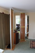
The WAF (wife acceptance factor) is truly appalling, especially with the day-glow yellow screen printing mesh on the backs. It’s probably a good thing there is no room for pot plants. However, the poor WAF appears to have been offset by the considerable improvement in sound quality – if I do a good job of the final clothing, I might yet be able to keep them in the lounge.
If I have managed to attached the picture correctly it shows he ESLs with one of the KEFs.
Thanks again to everyone at DIY, I’ve learned a lot.
Background:
Many, many, years ago, before I was married, I had the pleasure of owning a set of Quad ESL-57s. Of course they were intolerable objects because they would not support potted plants. So under considerable duress I sold them and replaced them with KEF CS7s, the largest of the constructor series KEF made, which had ample room for potted plants.
Needless to say, I always regretted selling the 57s; stereo was never quite as addictive after that. years later, in late 2007, a work colleague asked me a silly question that prompted me to look into ESLs again. To my great surprise there was a good sized DIY community, and so I began …..
Acknowledgements:
In addition to the many people who post here, I owe special thanks to Rob McKinlay of ER Audio, whose notes on his ESL kitsets convinced me that a DIY project was feasible. Also, Rob introduced me to the Loudspeaker and Headphone Handbook (Borwick) chapter on ESLs by Baxandall, which was a revelation. I also owe thanks to colleague PM, whose encyclopaedic memory I pick, and MP for helping me when I get stuck on some basic acoustics theory. Finally, thanks to Bolserst for the many off-line discussions and advice.
The design:
Towards the end of Baxandall’s chapter he derives the ‘Walker Equation’ relating SPL to stator current, for a line source – actually a floor-to-ceiling doublet. The equation has an awkward sqrt(f) dependence, which superficially at least, looks hard to equalise. However, the input impedance of an RC transmission line also has a sqrt(f) dependence. That means that an ESL comprised of many segments of equal capacitance, each linked to its neighbour by a single resistor, will have a flat frequency response. Following some computer modelling, I discovered that the symmetric version of this ESL has some additional magic – a polar response that varies as a second-order Butterworth response versus angle – that means (i) a broad listening area near the on axis position, (ii) no zeros and phase reversals in the frequency response (causing the phasiness that wide-segment ESLs are known for) and (iii) a graceful decrease in treble as the listener moves of axis. The results of the study were published in JAES as “A wide range electrostatic loudspeaker with a zero free polar response”. Contact me if you want a pre-print.
Practical build:
There are unfortunately a few beginners’ mistakes – I’ll explain as I go.
The finished ESL is about 500 mm wide by 2320mm tall – designed to fit under a 2400 mm ceiling. According to the design equations, the ESL has a nominally flat response down to 80 Hz, and then falls a way as sqrt(f) below that. In practice diaphragm resonance will boost the low frequency end – see later. I have chosen the smallest segments to be 12 mm wide to ensure minimal diffraction effects from the finite segment width.
The stators are manufactured from eight sections of 1100 mm x 384 mm x 0.8 mm PCB with 3 mm wide slots. They are reinforced with acrylic ribs glued in between the slots, every 40 mm. The spacers are also acrylic, 3.0 mm. The final stator-diaphragm spacing is less than 3mm due to half a dozen coats of acrylic lacquer. I have used copper tape as the stator ring on the rear stator, 3.5 um Mylar (supplied by Rob McKinlay), and spray-on Licron (NZ supplier available). I used the technique recommended by Rob to attach the diaphragm – stretched on an old glass shower panel using duct tape, to constant tension, and glued using slow setting epoxy.
Mistake 1: I designed the mechanical construction, in particular the split down the middle of each panel, before I discovered that an asymmetric ESL has a terrible polar response. So on each panel, one half is symmetric transmission line (for treble) and the other (bass end of the transmission line) is asymmetric. Not too much damage done – within a couple of dB of ideal.
Mistake 2: I assembled the PCB stators with the copper surface inwards, and the machined edges (followed by sanding and etching to minimise the problems) mean that I begin to get corona discharges at about 4 kV, and I’m having to run the ESL with half of the polarising voltage that I hoped for – 2.6 kV. However, I find I have sufficient area to still get them comfortably loud. The HT supplies have 100 M ohm in series to ensure constant charge operation (minimise distortion).
Mistake 3: For each of the two transformers in each ESL I used eight 20VA toroidal power transformers rated for 230Vac at 50 Hz. That gives me secondary voltages of up to plus-and-minus 2.6 kV at 50 Hz. I stripped the secondary windings off the transformers and put a single winding through a group of eight to make a sausage-like transformer. I did this with the hope of reducing the secondary winding thickness and hence reducing leakage inductance - but actually made no practical difference. I did a whole bunch of experiments on some 15 VA toroids (fo = 126 kHz), which suggested that a transformer of this design would have an unloaded resonance at 44 kHz. Unfortunately I spotted some 20VA transformers going cheap – but they turned out to have two 115Vac windings that had been wound simultaneously – hence very high winding capacitance, and the unloaded resonant frequency of the multicore transformer turned out to be only 23 kHz, and about 18 kHz with the ESL attached. So I lost a bit of the upper end (I can’t hear it anyway, but others might).
With the primaries of the transformers in parallel, I have a nominal step up ratio of 120. This gives the ESL a very low sensitivity, but on the plus side, my amplifier saturates before breakdown occurs, so I don’t need a protection circuit.
Conclusion:
More by good luck than good management, I finished up with a diaphragm resonance at 37 Hz – which means my ESLs have a -3dB cut-off a touch lower (response falls as f^2.5 below this). I used screen printing mesh to damp the resonance from a Q of about 30 down to perhaps 2 or 3 - this tops up the SPL below the nominal electrical cutoff at 80 Hz. So I estimate the final frequency response from 35 Hz to 18 kHz (guess + modelling – I hope to do measurements soon).
I am really pleased with the results, especially considering that I did not know what I was doing when I fixed most of the design parameters. Most of all I had not expected the fantastic bass – it goes further down than the KEFs did and with no crossovers etc, it’s seamless - fantastic. The midrange and tops are every bit as good as I hoped for – vocals, acoustic guitars, etc give eerily good imaging, and metallic instruments sound metallic. Most telling I think, on really dense, heavily orchestrated music, the music opens up – things I never heard on other systems.
They’re not as loud as the KEFs, but loud enough that I never have to turn them up to full volume. On first hearing, the line-source behaviour is weird – with the pair operating, the volume through my lounge is almost uniform – which gives the illusion of them getting louder as you move away. I could do with more cores in the transformers or higher polarising voltage – I have a couple of tracks with a very deep bass note where the core saturates and the amplifier protection circuit kicks in, but they have to be quite loud for this to happen.
The WAF (wife acceptance factor) is truly appalling, especially with the day-glow yellow screen printing mesh on the backs. It’s probably a good thing there is no room for pot plants. However, the poor WAF appears to have been offset by the considerable improvement in sound quality – if I do a good job of the final clothing, I might yet be able to keep them in the lounge.
If I have managed to attached the picture correctly it shows he ESLs with one of the KEFs.
Thanks again to everyone at DIY, I’ve learned a lot.
Very nice Build !!!
Thank You for Sharing!!!
I would be very interested in a copy of the JAES print.
I am not sure if I do have that one or not.
My next design is of a segmented design although much smaller.
I plan on applying the same rules to a much taller and slightly wider panel system eventually.
A Segmented Stator Desktop ESL
I think that a segmented panel system is something that is more beneficial for many reasons than the typical large flat panel types.
Cheers !!!
jer")
Thank You for Sharing!!!
I would be very interested in a copy of the JAES print.
I am not sure if I do have that one or not.
My next design is of a segmented design although much smaller.
I plan on applying the same rules to a much taller and slightly wider panel system eventually.
A Segmented Stator Desktop ESL
I think that a segmented panel system is something that is more beneficial for many reasons than the typical large flat panel types.
Cheers !!!
jer
Hi,
I´d also be interested in a copy
Q:
How did You manufacture the stators? Did You just route the slots or did You etch the copper before? Years ago I had searched long and wide for a PCB board manufacturer for oversized PCBs, because standard FR4 has good electrical properties for stators. IIRC around 500mm was the largest standard panel size they offered. Of course having the panels routed by a PCB manufacturer will probabely quite costly. Still though an promising material for flat panels.
jauu
Calvin
Hi Calvin
Standard max. PCB size is 450 mm x 600mm around here.
I had the PCBs machined at local cutting shop with a CNC router. Then, after machining, rough edges were sanded off. I then used masking tape and acrylic lacquer to provide the etch resist for the PCB. Had to make a large tank to etch them.
This was all before I figured out what I was doing. Second time around I would say that multiple sections either 450 mm or 600 mm wide is ideal. Put the copper on the outside and use 1W surface mount resistors for the transmission line.
regards
Good work!
How much capacity has each segment?
How much capacity has each segment?
Its long past time I shared my ESL experience with fellow DIYers here:
Background:
Many, many, years ago, before I was married, I had the pleasure of owning a set of Quad ESL-57s. Of course they were intolerable objects because they would not support potted plants. So under considerable duress I sold them and replaced them with KEF CS7s, the largest of the constructor series KEF made, which had ample room for potted plants.
Needless to say, I always regretted selling the 57s; stereo was never quite as addictive after that. years later, in late 2007, a work colleague asked me a silly question that prompted me to look into ESLs again. To my great surprise there was a good sized DIY community, and so I began …..
Acknowledgements:
In addition to the many people who post here, I owe special thanks to Rob McKinlay of ER Audio, whose notes on his ESL kitsets convinced me that a DIY project was feasible. Also, Rob introduced me to the Loudspeaker and Headphone Handbook (Borwick) chapter on ESLs by Baxandall, which was a revelation. I also owe thanks to colleague PM, whose encyclopaedic memory I pick, and MP for helping me when I get stuck on some basic acoustics theory. Finally, thanks to Bolserst for the many off-line discussions and advice.
The design:
Towards the end of Baxandall’s chapter he derives the ‘Walker Equation’ relating SPL to stator current, for a line source – actually a floor-to-ceiling doublet. The equation has an awkward sqrt(f) dependence, which superficially at least, looks hard to equalise. However, the input impedance of an RC transmission line also has a sqrt(f) dependence. That means that an ESL comprised of many segments of equal capacitance, each linked to its neighbour by a single resistor, will have a flat frequency response. Following some computer modelling, I discovered that the symmetric version of this ESL has some additional magic – a polar response that varies as a second-order Butterworth response versus angle – that means (i) a broad listening area near the on axis position, (ii) no zeros and phase reversals in the frequency response (causing the phasiness that wide-segment ESLs are known for) and (iii) a graceful decrease in treble as the listener moves of axis. The results of the study were published in JAES as “A wide range electrostatic loudspeaker with a zero free polar response”. Contact me if you want a pre-print.
Practical build:
There are unfortunately a few beginners’ mistakes – I’ll explain as I go.
The finished ESL is about 500 mm wide by 2320mm tall – designed to fit under a 2400 mm ceiling. According to the design equations, the ESL has a nominally flat response down to 80 Hz, and then falls a way as sqrt(f) below that. In practice diaphragm resonance will boost the low frequency end – see later. I have chosen the smallest segments to be 12 mm wide to ensure minimal diffraction effects from the finite segment width.
The stators are manufactured from eight sections of 1100 mm x 384 mm x 0.8 mm PCB with 3 mm wide slots. They are reinforced with acrylic ribs glued in between the slots, every 40 mm. The spacers are also acrylic, 3.0 mm. The final stator-diaphragm spacing is less than 3mm due to half a dozen coats of acrylic lacquer. I have used copper tape as the stator ring on the rear stator, 3.5 um Mylar (supplied by Rob McKinlay), and spray-on Licron (NZ supplier available). I used the technique recommended by Rob to attach the diaphragm – stretched on an old glass shower panel using duct tape, to constant tension, and glued using slow setting epoxy.
Mistake 1: I designed the mechanical construction, in particular the split down the middle of each panel, before I discovered that an asymmetric ESL has a terrible polar response. So on each panel, one half is symmetric transmission line (for treble) and the other (bass end of the transmission line) is asymmetric. Not too much damage done – within a couple of dB of ideal.
Mistake 2: I assembled the PCB stators with the copper surface inwards, and the machined edges (followed by sanding and etching to minimise the problems) mean that I begin to get corona discharges at about 4 kV, and I’m having to run the ESL with half of the polarising voltage that I hoped for – 2.6 kV. However, I find I have sufficient area to still get them comfortably loud. The HT supplies have 100 M ohm in series to ensure constant charge operation (minimise distortion).
Mistake 3: For each of the two transformers in each ESL I used eight 20VA toroidal power transformers rated for 230Vac at 50 Hz. That gives me secondary voltages of up to plus-and-minus 2.6 kV at 50 Hz. I stripped the secondary windings off the transformers and put a single winding through a group of eight to make a sausage-like transformer. I did this with the hope of reducing the secondary winding thickness and hence reducing leakage inductance - but actually made no practical difference. I did a whole bunch of experiments on some 15 VA toroids (fo = 126 kHz), which suggested that a transformer of this design would have an unloaded resonance at 44 kHz. Unfortunately I spotted some 20VA transformers going cheap – but they turned out to have two 115Vac windings that had been wound simultaneously – hence very high winding capacitance, and the unloaded resonant frequency of the multicore transformer turned out to be only 23 kHz, and about 18 kHz with the ESL attached. So I lost a bit of the upper end (I can’t hear it anyway, but others might).
With the primaries of the transformers in parallel, I have a nominal step up ratio of 120. This gives the ESL a very low sensitivity, but on the plus side, my amplifier saturates before breakdown occurs, so I don’t need a protection circuit.
Conclusion:
More by good luck than good management, I finished up with a diaphragm resonance at 37 Hz – which means my ESLs have a -3dB cut-off a touch lower (response falls as f^2.5 below this). I used screen printing mesh to damp the resonance from a Q of about 30 down to perhaps 2 or 3 - this tops up the SPL below the nominal electrical cutoff at 80 Hz. So I estimate the final frequency response from 35 Hz to 18 kHz (guess + modelling – I hope to do measurements soon).
I am really pleased with the results, especially considering that I did not know what I was doing when I fixed most of the design parameters. Most of all I had not expected the fantastic bass – it goes further down than the KEFs did and with no crossovers etc, it’s seamless - fantastic. The midrange and tops are every bit as good as I hoped for – vocals, acoustic guitars, etc give eerily good imaging, and metallic instruments sound metallic. Most telling I think, on really dense, heavily orchestrated music, the music opens up – things I never heard on other systems.
They’re not as loud as the KEFs, but loud enough that I never have to turn them up to full volume. On first hearing, the line-source behaviour is weird – with the pair operating, the volume through my lounge is almost uniform – which gives the illusion of them getting louder as you move away. I could do with more cores in the transformers or higher polarising voltage – I have a couple of tracks with a very deep bass note where the core saturates and the amplifier protection circuit kicks in, but they have to be quite loud for this to happen.
The WAF (wife acceptance factor) is truly appalling, especially with the day-glow yellow screen printing mesh on the backs. It’s probably a good thing there is no room for pot plants. However, the poor WAF appears to have been offset by the considerable improvement in sound quality – if I do a good job of the final clothing, I might yet be able to keep them in the lounge.
If I have managed to attached the picture correctly it shows he ESLs with one of the KEFs.
Thanks again to everyone at DIY, I’ve learned a lot.
Hello Golfnut,
Congrats on creating a practical working ESL that successfully implements the theory in your AES paper.
Anybody who has attempted to build full range ESLs knows the difficulties involved.
And this was your first build!!! Most impressive perseverance, and results.
@Calvin, geraldfryjr
The AES paper has been discussed several times on the forum.
In one thread I posted an Excel spreadsheet that incorporates concepts from the paper.
It allows you to quickly get an idea what different panel width and segmentation sizes are capable of in terms of bandwidth & SPL.
http://www.diyaudio.com/forums/planars-exotics/48120-experiences-esl-directivity-9.html#post2218526
http://www.diyaudio.com/forums/planars-exotics/48120-experiences-esl-directivity-7.html#post2204784
The paper is identified in post #43, and there is pretty good discussion throughout the thread, starting from post # 52 where kavermei summarized the AES paper.
http://www.diyaudio.com/forums/planars-exotics/48120-experiences-esl-directivity-6.html#post2202327
Hi,
I think I remember a 80s or 90s patent (probabely even earlier as it seems that everything regarding ESLs had been invented already in the first 5minutes since the first thought on that matter was written down) the concept of a high impedance and varying high impedance stator was described.
Using todays printing technology one might think of printing a high-ohmic ink onto a punched, routed or cast insulator. An idea I'm rolling in my head for a couple of years now is a stator manufactured completely from clear transparent materials. Transparent inks are offered in various resistance ranges. So all one needs to design the 'invisible' ESL is there
jauu
Calvin
Ps. just in case someone thinks he could patent this idea like Sanders got an patent on an PCB stator in 2005 that Beveridge had done decades earlier already ..... No! Its open source now
Pps. Stephen, could never get Your script running on my pc.
esltransformer: the nominal capacitance of the panels is about 620 pF. The lacquer coating was put on afterwards, so finished capacitance is greater, maybe 700 pF. The capacitance of the smallest segment at the beginning of the transmission line is about 20 pF – the larger segments at the end of the transmission line are about 3 times that.
Bolserst: Thanks for posting the links.
Calvin: Yes, there is a patent, I can’t remember whose, that describes a conductive stator, effectively with the transmission line built in. From what I recall, the author did not envisage a line source. I have looked into the possibility and there are conductive plastic sheets available that would do the job, including acrylic. The problem is that they are intended for antistatic applications and the uniformity of resistance is not that good – may be good enough though.
Stephen, could never get Your script running on my pc.
Hmmm, I'm not sure why you would be having problems with the Line source Excel spreadsheet.
The are no unusual requirements to run it.
Feel free to contact me via email or PM to sort it out.
I know you had problems with the near/intermediate/field field Excel spreadsheet because it required the Analysis ToolPak be loaded and you did not have the installation CD.
http://www.diyaudio.com/forums/plan...r-esl-simulator-esl_seg_ui-3.html#post2916242
link to the near/intermediate/field field Excel spreadsheet:
http://www.diyaudio.com/forums/plan...r-esl-simulator-esl_seg_ui-2.html#post2913884
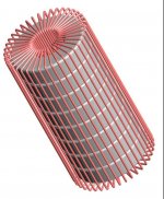
For those curious about golfnut's "sausage-like" transformers, here is a pictorial representation of the stacked toroid concept that Alexberg posted in another thread:
http://www.diyaudio.com/forums/plan...trostatic-headphone-driver-7.html#post3372969
Attachments
Hi,
I rather thought of pure clear acrylics with a printed-on layer of conductive transparent ink and sealed with an transparent insulative coating/laquer. The membrane could be transparent as well as the membrane coating. The stators could be routed from acrylic sheets and heat treated after to get the matted surfaces clear again and the sharp edges rounded, or it may even be better cast into a mould, thereby allowing to include spacers and stiffening ribs at the same. The conductive ink may be printed on with standard inkjet printer technology. There are several different formulations over a certain ohmic range. Lowohmic inks may be used as replacement for cabling and copper charge ring. A special transparent laquer, commonly used for insulating and sealing PCBs may be used as insulative layer also. It may be possible to replace the insulative coating by a second cast of acrylics, thereby sealing the conductive areas completely within the stator structure.
If not cast into the stator structure, 3M's clear transparent tapes may be used as spacers. The mounting frame may of course be made from standard acrylic material again. So all is there ... the idea, the materials an the technologies. The only thing I'm still missing ...... and that's the point You Gerald my friend, come into play, are transparent toroids
jauu
Calvin
Last edited:
Golfnut, The connections can be quite easily made!
Since the material is basically painted on you can just paint right over a few connecting foil strips where ever a connection is needed as I have done here,
http://www.diyaudio.com/forums/planars-exotics/109789-esl-diaphragm-coating-7.html#post2142822
Or you can use a simple pressure contact method as well.
I used both techniques in that particular design to connect to the diaphragm and can be used in the stator construction as well.
jer
Hi Calvin
I wouldn't use a router to cut the acrylic, laser cutting is much faster and leaves a rounded edge. Screen printed inks sounds good though - how would you make the connections to the resistors?
I would not use laser on acrylic: it creates extreme stress at the edges and one have to anneal the whole thing and still you'll get the whole bunch of whisker kinda cracks. Proper router bit would yield any kind of edge you like.
- Status
- This old topic is closed. If you want to reopen this topic, contact a moderator using the "Report Post" button.
- Home
- Loudspeakers
- Planars & Exotics
- Another segmented ESL