After have following båndsei´s thread about DIY AMT, I thought it is best if I start an own thread for the ones I´m making so I don´t clutter his thread with questions on my construction.
So this is a homage to båndsei´s thread, I thank him for all his help (they were others of course) and I hope that my work will be benificial for his in the end.
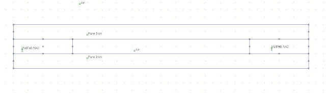
I´ll start with the motor, this is how it looks in FEMM seen from above:
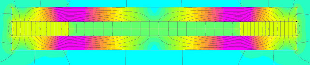
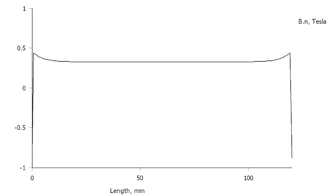
Simulation shows an even field in the gap:
The field is 0,325 T in the middle of the curve:
The field will be less as the iron actually is a bunch of 3x10 mm rods with 3 mm air in between (the green stuff):
Total size of motor is 200 mm wide, 160 mm high and 40 mm thick.
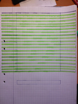
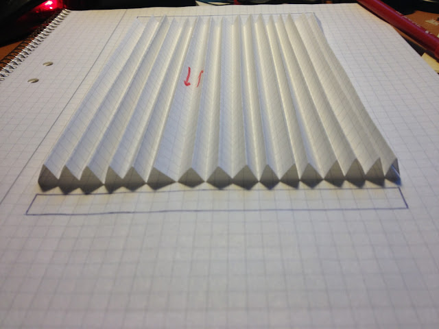
Membrane will be 250 mm wide and 160 mm high folded to fit into a 120 mm wide, 160 mm high and 10 mm deep magnetic gap:
There´s a lot of work before this is ready...
So this is a homage to båndsei´s thread, I thank him for all his help (they were others of course) and I hope that my work will be benificial for his in the end.
I´ll start with the motor, this is how it looks in FEMM seen from above:
Simulation shows an even field in the gap:
The field is 0,325 T in the middle of the curve:
The field will be less as the iron actually is a bunch of 3x10 mm rods with 3 mm air in between (the green stuff):
Total size of motor is 200 mm wide, 160 mm high and 40 mm thick.
Membrane will be 250 mm wide and 160 mm high folded to fit into a 120 mm wide, 160 mm high and 10 mm deep magnetic gap:
There´s a lot of work before this is ready...
Total size of motor is 200 mm wide, 160 mm high and 40 mm thick.
Membrane will be 250 mm wide and 160 mm high folded to fit into a 120 mm wide, 160 mm high and 10 mm deep magnetic gap:
There´s a lot of work before this is ready...
It will be interesting to follow this project.
I think your calculations are a bit off - you will have 8 to 10 mm between the center of the folds...
The slot loading will then only be approximately gone (no slot loading) and my experience then is that you get a driver that are radiating from a 45 degree angle and without slot loading.
I do not know how this may work in practice, but I see a multitude of issues that will and can give you trouble.
I would have expected the diaphragm width to fill the 120 mm should have been increased from the 250 mm up to somewhere between 500 mm to 2000 mm to achieve slot loading properties.
However the forces may cause the top and bottom of the folds to somehow wobble in and out, and the middle of the pleats will curve in and out. So maybe this will give an interesting kind of "radiator" effect..
Last edited:


No, this is the front (or back, it depends what will parts that will look the best).Dont you need some iron cut at 40mm to place in betvine.
Bernt.


No, this is the front (or back, it depends what will parts that will look the best).
Sorry, I got your question wrong

I thought about that, having 40 mm iron in-between the 200 mm rods that is, but I don´t think strenghtens the field of the gap anyway.
The rationale for this is that I observed that I couldn´t get two rod close together on the magnet without using force. They actually befare soft magnets themselves and repelled each other.

Design thought One
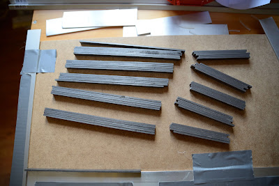
Just finished the second pair and I´ll probably assemble the motors tonight.
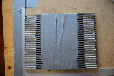
Attaching the magnets to the "cattle guard/grid" will probably be a tough job.
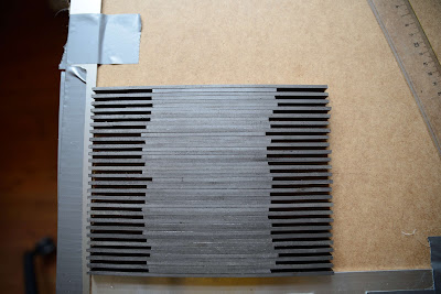
So I was thinking: Does the front part grid and the back part grid really need to be aligned? Having them offset by 3 mm would result in a so to speak non-see through motor.
Just finished the second pair and I´ll probably assemble the motors tonight.
Attaching the magnets to the "cattle guard/grid" will probably be a tough job.
So I was thinking: Does the front part grid and the back part grid really need to be aligned? Having them offset by 3 mm would result in a so to speak non-see through motor.
Last edited:
Good morning to you as well.Good morning Solhaga.
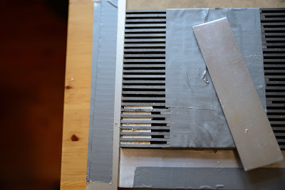
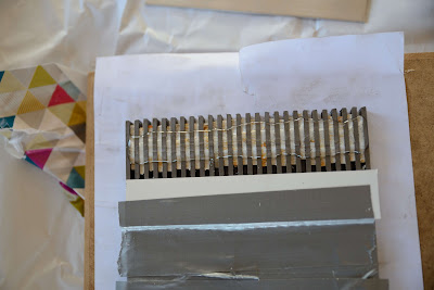
DONT!! place all the magnets on one grid and try to place the other on top.
Place a 10mm. thick wood at the one side and push some magnets sideways in at the other.
Move the wood a bit and push or tap some in.
Try to align them.
Good Luck
Bernt
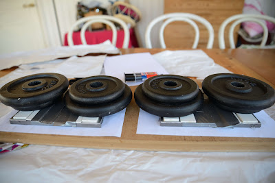
I been thinking in that direction. Another way would be to place all the magnets on one grid and have a much thicker stack than 10 mm in the middle and then removing "cards" in the stack and thereby lowering the other grid towards the other.
Do you think glueing of the magnets is necessary or does one do that afterwards if needed?
I dont think you can drag the "cards out as the stack gets thin
No need for gluing i think,but the magnets are repelling each other.You might have to fasten first and last in the row.
Bernt
Thanks for the advice. I´ll go for your suggestion. Great idea to fasten the first and last magnet in the row.
Perhaps the first one can be glued and the last one fasten with a clamp so there´s room for adjustments.
I plan to glue a 30 mm x 160 mm aluminum plate on the outside of the magnets just as the front and back plates.
Also inside I plan to glue a 1 mm thick 10 mm x 160 mm aluminium strip to get an even surface for the membrane.
- Status
- This old topic is closed. If you want to reopen this topic, contact a moderator using the "Report Post" button.
- Home
- Loudspeakers
- Planars & Exotics
- Yet another DIY AMT