Thanks ,Bolserst, The xls files help out a lot !!
I have a pretty good understanding but it hasn't completely sunk in yet as far as the two points in the curve is concerned.
I have read this over a few times in the Walker and Baxandal papers but I just don't have it as second nature yet,But I will in time.
The simulations do portray very close to what I had measured with my last little panel before it shorted out on me.
As I have done many measurements at various distances within 1 meter and less.
Only I had a few issues because they weren't done in a good free space and had lots of early reflections to decipher through.
But these were good for showing what is happening in a real world situation.
I still have those curves and I will dig them up to compare too and this will help me even more.
I was thinking that the little panel will act as a point source from a large distance but I never got that far to try it out,thus the need to build new panels.
I have a fresh memory of how the little panel sounded and it will be interesting to find out how a panel that is a little bit wider (50%) will act.
It is a little deceiving that the segmented ESL simulator does not take the lower frequency's into perspective, Although this is what I had expected as well.
jer")
I have a pretty good understanding but it hasn't completely sunk in yet as far as the two points in the curve is concerned.
I have read this over a few times in the Walker and Baxandal papers but I just don't have it as second nature yet,But I will in time.
The simulations do portray very close to what I had measured with my last little panel before it shorted out on me.
As I have done many measurements at various distances within 1 meter and less.
Only I had a few issues because they weren't done in a good free space and had lots of early reflections to decipher through.
But these were good for showing what is happening in a real world situation.
I still have those curves and I will dig them up to compare too and this will help me even more.
I was thinking that the little panel will act as a point source from a large distance but I never got that far to try it out,thus the need to build new panels.
I have a fresh memory of how the little panel sounded and it will be interesting to find out how a panel that is a little bit wider (50%) will act.
It is a little deceiving that the segmented ESL simulator does not take the lower frequency's into perspective, Although this is what I had expected as well.
jer
Hi,
Stephen, with any change in the resonance and Q fields the response curve+Q vanishes.
jauu
Calvin
Hmmmm...the resonance curve calculation does use complex variables.
Perhaps you don't have the Analysis ToolPak loaded in the Excel Add-Ins.
Which version of Excel are you using?
2002
I believe with Excel 2002 you can activate the Analysis ToolPak by selecting Add-Ins from the Tools drop-down menu.
Then just check the Analysis ToolPak box and click OK. The spreadsheet calculations should start working.
If this doesn't solve your problem, or the Analysis ToolPak doesn't show up in your available list of Add-Ins, send me a PM or email and we'll figure it out off-thread.
Segmented Wire Stator ESL Simulator (Q & A)
I've had quite a few questions sent to me concerning the segmented ESL simulator.
There were three that came up several times, so figured it might be worth posting them here.
Q1: "If the height entered for the line source doesn't change the calculated response since line source behavior is assumed, then why even have the option to enter a height?"
A1: "The height is still needed to determine the capacitance of each segment of the ESL panel. This capacitance directly affects the LP filter behavior calculated based on the ladder resistors you enter"
Q2: "How does this calculator compare to the AES paper on segmented ESLs and the simple sectioned line source Excel spreadsheet you posted here:"
http://www.diyaudio.com/forums/planars-exotics/48120-experiences-esl-directivity-9.html#post2218526
A2: "All are in agreement"
Attachment 1: For comparison, let's take the example of a 20 segment ESL shown in Figure 9 of the AES paper. The solid line shows the simple model developed in the paper which is used in the Excel spreadsheet. The + symbols show the curve for the rigorous calculation of the segmented ESL using the same ladder resistor network as for the simple model.
Attachment 2: Using the segmented ESL simulator to model the same 20 segment ESL.
Attachment 3: Scaling Attachment 2 and overlaying with Attachment 1, you can see that the blue line is in good agreement with the curve of + symbols.
Q3: "Why does using the ladder resistor values from the AES simple model result in a +1dB bump just before the LF roll-off?"
A3: "As explained in the AES paper, the simple model assumes an infinite number of segments. Using a finite number results in an impedance miss-match at the end of the ladder-resistor RC line. If this concerns you, you can flatten the bump by terminating with some additional dummy load R-C sections as shown in Attachment 1. Alternatively, I have found that increasing the value of the ladder resistors for the last couple sections by about 50% gets the job done as well. Personally, I wouldn't lose any sleep over it."
Attachments
Segmented Wire Stator ESL Simulator (Physical Build)
Somebody just reminded me I never posted the clarification I promised in post # 18 on what exactly the simulator is physically modeling.
I think the best way to do this is with an example...lets use the input parameters geraldfryjr selected in post #13.
http://www.diyaudio.com/forums/plan...r-esl-simulator-esl_seg_ui-2.html#post2912641
It was a 10 segment design with 2 wires entered for each section.
The segmentation resistors were: 180k,3.9M,5M,5M,5M,5M,5M,10M,10M,10M.
What the program is modeling is shown in the top figure of the attachment.
This is also how you would physically build and wire the segmented ESL stators.
Section #1 is the center section, made up of 2 wires with a capacitance of about 4pF. It is fed by the specified 180K ladder resistors.
Section #2 is made up of 2 wires to the left of section #1 AND 2 wires to the right of section #1. Both left and right portions of section #2 are fed from section #1 with the specified 3.9M ladder resistors.
Section #3 is made up of 2 wires to the left of the left portion of section #2 AND 2 wires to the right of the right portion of section #2. Both left and right portions of section #3 are fed from the adjacent portion of section#2 with the specified 5M ladder resistors.
etc...
To simplify modeling in SPICE, you can fold the left half of the ESL panel about the center section and combine the left and right portions of the outer sections in parallel as shown in the middle figure of the Attachment. The lower figure in the Attachment shows the resulting R and C values when the paralleled portions are combined.
Key point of possible confusion:
If you specify the same number of wires for each section in the entry block, what you are actually modeling is an ESL that has its first segment half the size of the remaining segments.
The lower figure in the Attachment makes this clear.
.
Attachments
Hi,
is there a link to the AES paper?
The abovesimulation is of course a simulation. Therefore it should be taken with a grain of salt.
Two points:
a) The number of segments doesn´t need to be so large. Typically 2-3 electrical segmentations, i.e 3-5 mechanical segments are sufficient.
As a rule of thumb I´d use max. 3 segmentations with the segment area increasing by a factor of 4 (2times doubling).
b) the capacitance values of each segment is very small. This means high impedance values, hence high transformation faktors of the audio tranny. practical values should be at least 10 times higher.
c) whats the purpose of the 180k resistors? If they are intended for damping HF resonace and to tune HF-response the value will in praxis probabely be lower. 360k as in the example already attenuates at 20kHz with -0,8dB.
jauu
Calvin
Yes,I have had similar results using a lesser amount of segments.
In this configuration it was the flattest response and widest dispersion I could get for a first few go rounds.
As I haven't played with it much lately.
I have been waiting on the weather in order to start painting the stator pieces outside.
Yes ,the value of the 180k resistors effect the overall slope of the high frequencys in the simulations and their actual results I will find out when I get a sample built.
It almost seems to me that they may not even be needed as without them there is a boost at the high end of about atleast 2db without them.
I will have to play with the simulation again to verify the amount of this.
This makes the off center at 15 degrees or so the very flat range and this may most likely be better depending on what the angle of the panel is to the listeners position.
And may compensate for my slight hearing deficiency's at that end of the spectrum as well (he,he).
With my pattern on such a small panel it certainly points to the fact that only 3 or 4 sections are really necessary.
I will be able to experiment with this on the the panel as it will be built in such a manner to do so.
Cheers !!
jer
Hi,
the 180k -in fact its 360k because of the series connection, as well as all the other doubled resistors which may be replaced by singles also- I would omit with. Instead I´d use a low ohmic value on the primary side. Its more practical to tame the HF resonance on the primary side. Besides not to need to worry about getting shocked, the resistor on the primary always is kinda safety measurement for the amp in case something weird happens with the audio tranny.
jauu
Calvin
Hi,
AES E-Library Wide-Range Electrostatic Loudspeaker with a Zero-Free Polar Response
http://www.diyaudio.com/forums/planars-exotics/48120-experiences-esl-directivity-6.html#post2202327
Yes, it is a simulation, but I have found it to match very closely to what I get in practice.
The reason for differences are, of course, based on what assumptions were made in the calculations.
A few practical matters I have mentioned before that are ignored by the calculations:
1) Diaphragm resonance behavior at LF is ignored
2) Transformer leakage inductance behavior at HF is ignored
3) Section to section capacitive coupling is ignored
4) HF loss due to the inertia of the diaphragm and/or the inertia of air in the holes in the stators is ignored.
b) Yeah, using the values for geraldfryjr’s very small panel may have not been the best example. For my 2m tall line sources capacitance is about 100pF per section.
c) The 180k resistors are there to flatten the rising response of the central segment. As you state, in practice the value will need to be adjusted somewhat to account for items 2) & 4) mentioned above. Note that these resistors are often implemented as a low value resistor on the primary side of the transformer where they can also provide some amount of resistance to core saturation. I do this, as does Audiostatic and Capaciti.
I agree concerning the 180K resistors feeding the first section. See c) above.
also, middle of following post.
http://www.diyaudio.com/forums/planars-exotics/48120-experiences-esl-directivity-8.html#post2214797
and
http://www.diyaudio.com/forums/planars-exotics/48120-experiences-esl-directivity-8.html#post2215564
For the remaining sections, you could combined and replace series connected resistors with singles for modeling purposes.
But, when building the panel you need to segment both the front and rear stators, so you need to keep both of the resistors…one connected between segments of the front stator, the other between segments of the rear stator.
The AES paper has been discussed a couple times on the forum.is there a link to the AES paper?
The above simulation is of course a simulation. Therefore it should be taken with a grain of salt.
AES E-Library Wide-Range Electrostatic Loudspeaker with a Zero-Free Polar Response
http://www.diyaudio.com/forums/planars-exotics/48120-experiences-esl-directivity-6.html#post2202327
Yes, it is a simulation, but I have found it to match very closely to what I get in practice.
The reason for differences are, of course, based on what assumptions were made in the calculations.
A few practical matters I have mentioned before that are ignored by the calculations:
1) Diaphragm resonance behavior at LF is ignored
2) Transformer leakage inductance behavior at HF is ignored
3) Section to section capacitive coupling is ignored
4) HF loss due to the inertia of the diaphragm and/or the inertia of air in the holes in the stators is ignored.
a) I agree, good results can be had with 3 – 5 segments. Using segments with increasing area as you recommend will enable you to achieve a wider flat bandwidth than if the same number of equal sized segments is used.(ie less total width). But, if your goal is to achieve constant directivity and wide dispersion for f > 10kHz, you have to use many equal sized segments. FWIW, I use equal sized segments for the first 4 sections, and then incrementally larger for the remaining segments.Two points:
a) The number of segments doesn´t need to be so large. Typically 2-3 electrical segmentations, i.e 3-5 mechanical segments are sufficient.
As a rule of thumb I´d use max. 3 segmentations with the segment area increasing by a factor of 4 (2times doubling).
b) the capacitance values of each segment is very small. This means high impedance values, hence high transformation faktors of the audio tranny. practical values should be at least 10 times higher.
c) whats the purpose of the 180k resistors? If they are intended for damping HF resonace and to tune HF-response the value will in praxis probabely be lower. 360k as in the example already attenuates at 20kHz with -0,8dB.
b) Yeah, using the values for geraldfryjr’s very small panel may have not been the best example. For my 2m tall line sources capacitance is about 100pF per section.
c) The 180k resistors are there to flatten the rising response of the central segment. As you state, in practice the value will need to be adjusted somewhat to account for items 2) & 4) mentioned above. Note that these resistors are often implemented as a low value resistor on the primary side of the transformer where they can also provide some amount of resistance to core saturation. I do this, as does Audiostatic and Capaciti.
The 180k -in fact its 360k because of the series connection, as well as all the other doubled resistors which may be replaced by singles also- I would omit with. Instead I´d use a low ohmic value on the primary side. Its more practical to tame the HF resonance on the primary side. Besides not to need to worry about getting shocked, the resistor on the primary always is kinda safety measurement for the amp in case something weird happens with the audio tranny.
I agree concerning the 180K resistors feeding the first section. See c) above.
also, middle of following post.
http://www.diyaudio.com/forums/planars-exotics/48120-experiences-esl-directivity-8.html#post2214797
and
http://www.diyaudio.com/forums/planars-exotics/48120-experiences-esl-directivity-8.html#post2215564
For the remaining sections, you could combined and replace series connected resistors with singles for modeling purposes.
But, when building the panel you need to segment both the front and rear stators, so you need to keep both of the resistors…one connected between segments of the front stator, the other between segments of the rear stator.
Last edited:
I have been playing with the segmentation program again today.
And one thing that I did not understand until now was ow the groups of wires are labeled in the program.
What I did figure out was that the very first number in the list is the center group of wires and the succeeding numbers represent each next group on either side of the center group.
I had originally thought that the first number was half of the number of wires in the center group,So when I started with 2 I thought that there was 4 wires in the center group and this was throwing off my count and spacing calculations.
I am glad to say that I have it straight now!!
Now I have come up with a new pattern with half as many sections and still looks very good.
Also it was mentioned about the 6db rise in response and this is understood.
My little panel does show that it is flat when the microphone is right on the diagphram at a few cm's away.
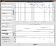
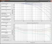
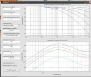
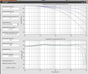
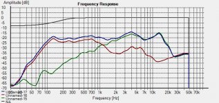
However, I have measured the same 6 db rise at the listening position of about .5 meter as well as 1 meter and both is shown in the first chart.
So, even this is considered nearfield and does show the rise in response in this range.
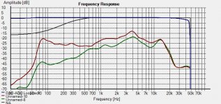
The second chart shows the ESL and the woofer in fullrange use.
These measurements were done the the Dayton Measurement microphone.
The new criteria for the simulation is the same as the earlier one except for the number of segments and the resistor values.
As well as the transformation ratio has been increased along with the bias voltage to match the test setup.
At a 5Kv bias I was getting around 89db of sensitivity and increasing the bias to 7kv in the simulation nearly match's what I have measured in realtime tests.
Although I was not able to write down any data to completely confirm this as the panel had given out before hand.
But, I did confirm a 6 db increase in SPL with a 100% increase in bias voltage and a 3 db increase of SPL with just 50% increase of the bias voltage.
I did do this using several different starting bias voltage points as well.
In the simulation I used a .5 meter distance also.
An interesting thing occurred of results when I did a simulation of the panel with no segmentation, It showed that the panels response would only have a rise of 3db per octave.
My question is, Is this the compensation for a line source?
If so I have some very nice simulations with a down sloping frequency response rather than a flat frequency response that I may have to use instead.
As it will be just a change of the resistors is all.
In the new simulation and many others there is a hump at around 200hz and this is very hard to get rid of in some of the charts I have done.
It is also the staring point of the down sloping simulations ones as well.
But, In this one it is only about a .5db to .75db boost and I doubt this would be an issue especially in that range.
I am in the process of doing this build so we shall see in the testing as to how it is going to turn out.
Cheers!!!
jer
And one thing that I did not understand until now was ow the groups of wires are labeled in the program.
What I did figure out was that the very first number in the list is the center group of wires and the succeeding numbers represent each next group on either side of the center group.
I had originally thought that the first number was half of the number of wires in the center group,So when I started with 2 I thought that there was 4 wires in the center group and this was throwing off my count and spacing calculations.
I am glad to say that I have it straight now!!
Now I have come up with a new pattern with half as many sections and still looks very good.
Also it was mentioned about the 6db rise in response and this is understood.
My little panel does show that it is flat when the microphone is right on the diagphram at a few cm's away.
However, I have measured the same 6 db rise at the listening position of about .5 meter as well as 1 meter and both is shown in the first chart.
So, even this is considered nearfield and does show the rise in response in this range.
The second chart shows the ESL and the woofer in fullrange use.
These measurements were done the the Dayton Measurement microphone.
The new criteria for the simulation is the same as the earlier one except for the number of segments and the resistor values.
As well as the transformation ratio has been increased along with the bias voltage to match the test setup.
At a 5Kv bias I was getting around 89db of sensitivity and increasing the bias to 7kv in the simulation nearly match's what I have measured in realtime tests.
Although I was not able to write down any data to completely confirm this as the panel had given out before hand.
But, I did confirm a 6 db increase in SPL with a 100% increase in bias voltage and a 3 db increase of SPL with just 50% increase of the bias voltage.
I did do this using several different starting bias voltage points as well.
In the simulation I used a .5 meter distance also.
An interesting thing occurred of results when I did a simulation of the panel with no segmentation, It showed that the panels response would only have a rise of 3db per octave.
My question is, Is this the compensation for a line source?
If so I have some very nice simulations with a down sloping frequency response rather than a flat frequency response that I may have to use instead.
As it will be just a change of the resistors is all.
In the new simulation and many others there is a hump at around 200hz and this is very hard to get rid of in some of the charts I have done.
It is also the staring point of the down sloping simulations ones as well.
But, In this one it is only about a .5db to .75db boost and I doubt this would be an issue especially in that range.
I am in the process of doing this build so we shall see in the testing as to how it is going to turn out.
Cheers!!!
jer
Attachments
-
 ESL SEG 12 HF Roll off 10Khz-20Khz.jpg150.4 KB · Views: 160
 -
 ESL SEG 12 FR 200Hz-20Khz.jpg167.4 KB · Views: 161
 -
 ESL SEG 12 Bump at 200Hz.jpg155.7 KB · Views: 637
 -
 ESL SEG 12.jpg177.3 KB · Views: 644
 -
 Small esl-woofer.jpg249.2 KB · Views: 647
 -
 Small esl.jpg248.1 KB · Views: 658
 -
 Small esl test setup.jpg74.7 KB · Views: 683
Last edited:
Hello geraldfryjr,
Good to see you are still at it, working to get simulation & measurement to agree.
Glad you got it figured out now.
http://www.diyaudio.com/forums/plan...r-esl-simulator-esl_seg_ui-3.html#post2942303
Yes, an uncompensated line source has a response that rises +3dB/octave. Reducing the driven area with increasing frequency with segmentation is what flattens the response. Remember, the simulator assumes the dimensions you enter for your panel will describe an ESL that behaves as a line source, so it always uses the +3dB/oct slope for the starting(non-segmented) response. It is up to you to make sure that is the case.
You might reread post#20.
http://www.diyaudio.com/forums/plan...r-esl-simulator-esl_seg_ui-2.html#post2913884
When measured at 1m, your small panel will behave more like a point source than a line source over most of the frequency range with a +6dB/oct slope rather than +3dB/oct.
More information in Question 3) at bottom of post#27
http://www.diyaudio.com/forums/plan...r-esl-simulator-esl_seg_ui-3.html#post2942226
Good to see you are still at it, working to get simulation & measurement to agree.
This was the key point of possible confusion I tried to address in post #13.And one thing that I did not understand until now was ow the groups of wires are labeled in the program. What I did figure out was that the very first number in the list is the center group of wires and the succeeding numbers represent each next group on either side of the center group.
Glad you got it figured out now.
http://www.diyaudio.com/forums/plan...r-esl-simulator-esl_seg_ui-3.html#post2942303
An interesting thing occurred of results when I did a simulation of the panel with no segmentation, It showed that the panels response would only have a rise of 3db per octave. My question is, Is this the compensation for a line source?
Yes, an uncompensated line source has a response that rises +3dB/octave. Reducing the driven area with increasing frequency with segmentation is what flattens the response. Remember, the simulator assumes the dimensions you enter for your panel will describe an ESL that behaves as a line source, so it always uses the +3dB/oct slope for the starting(non-segmented) response. It is up to you to make sure that is the case.
You might reread post#20.
http://www.diyaudio.com/forums/plan...r-esl-simulator-esl_seg_ui-2.html#post2913884
When measured at 1m, your small panel will behave more like a point source than a line source over most of the frequency range with a +6dB/oct slope rather than +3dB/oct.
The hump is from impedance miss-match at the end of the R-C ladder network. The AES paper had some suggestions on how to deal with it.In the new simulation and many others there is a hump at around 200hz and this is very hard to get rid of in some of the charts I have done.
More information in Question 3) at bottom of post#27
http://www.diyaudio.com/forums/plan...r-esl-simulator-esl_seg_ui-3.html#post2942226
Thanks Bolserst it is becoming more clear to me now.
In further studying after my last post I had modeled the results from the your excel file and had found this same compensation.
The results of my earlier simulations that had this compensation and had a much flatter and extended roll off for all of the angles from 10Khz and above.
This when I started to wonder what was happening and which is the proper way to do this.
Second,
Without doing some spice simulations yet, I am finding that the very first resistor is of a much lower value and this resistor needs to be a much higher wattage than I anticipated for the higher voltages.
Realizing that this controls the overall slope compensation my idea is to eliminate this resistor and use active equalization instead and leave the rest of the resistors as normal for the panels off center equalization.
Even by using a resistor in the primary brings the value into a more workable range.
But, It will still need to be in a rather large power resistor and is a waste of precious amplifier power as well.
Not to mention the cost and size of such resistors.
I will know more of the results once I get it running.
On the last testing of the little panel the dispersion wasn't too bad and I did have to cut back the highs a bit as a form of this compensation, and, this greatly reduced the ear fatigue.
But even at the very close range the drop of highs in the 15 degree to 30 degree off center range was noticeable with some movement.
Bettering the dispersion to the 30 degree range will be a vast improvement even (especially) for nearfield listening.
Even if this means a 1 db or 1.5 db drop of SPL's in the off center range.
I believe that this will be much less of noticeable difference as the frequency response will still be flat rather than suddenly dropping off.
I am expecting that this will help for when I get up and walk around as well.
When I got up to walk around the room it still wasn't too bad.
It just lacked the crispness and sparkle of the high end is all, as they played plenty loud enough for me to hear plain as day when I went downstairs as well.
Also they definitely didn't have the beaming issues that my 8" wide panels had as I now understand why this is.
Even at a much greater distance of 12' I still felt like my head was in a vice compared to the little panels and is what made me fancy them more back in 2003 when I made them and knew nothing about hows and why's about them.
Thanks for your help !!!
jer
Last edited:
Its interesting where does this program come from.
Anybody knows the developer? If I could get the source code I could translate to English + Make save/load function.
Refer to post#1 and #9 in this thread for downloading and extracting the program files.
It is a MATLAB based program.
All of the window layout and labels are contained in the file "esl_seg_ui.fig".
I have tried modifying it with MATLAB's GUI editor, changing all the labels to English.
But, when I save the layout file and try to running the program again with this file it crashes.
I am not familiar with creating and linking GUI interfaces with MATLAB.
If you are, I'm sure you can get it working in short order.
....The the only thing I am wondering is how do you determine the wattage of the resistors.
I do plan on doing sweep tests on the panels after they are built and I don't need any failures.
I will try to plot this up in circuit maker and as well as LTSpice as I am just now learning to use that program.
If this works as planned then my planned 6' (2 X 3 foot peices stacked) line source will be perfect for my current system.
Any Suggestions?
jer
As you probably know, the Acoustat Spectra series is a segmented ESL. The various sectors are fed with resistors acting against the capacitance of the panel to effect the appropriate roll-off frequencies. Those resistors are axial-lead models, available from several manufacturers (Dale/Vishay is one) rated for 5-watts at 5-kV. This rating seems to be quite adequate for the task, as I am not aware of any field-failures.
Refer to post#1 and #9 in this thread for downloading and extracting the program files.
It is a MATLAB based program.
All of the window layout and labels are contained in the file "esl_seg_ui.fig".
I have tried modifying it with MATLAB's GUI editor, changing all the labels to English.
But, when I save the layout file and try to running the program again with this file it crashes.
I am not familiar with creating and linking GUI interfaces with MATLAB.
If you are, I'm sure you can get it working in short order.
Looks like its a compiled MATLAB program, so simply editing .fig file is not possible. It had to be translated with a hex editor.
Maybe I will implement external project saver/loader but that's a bigger job so no promises
.First extract all .zip files and then run self-extracting archive. I could not post here otherwise because of file size and type restriction.
Attachments
-
esl_seg_ui.EN.part06.zip955.3 KB · Views: 226
-
esl_seg_ui.EN.part05.zip956.4 KB · Views: 217
-
esl_seg_ui.EN.part04.zip957.3 KB · Views: 210
-
esl_seg_ui.EN.part03.zip957.3 KB · Views: 216
-
esl_seg_ui.EN.part02.zip956.6 KB · Views: 223
-
esl_seg_ui.EN.part01.zip904.7 KB · Views: 316
-
esl_seg_ui.EN.part07.zip751.1 KB · Views: 210
- Status
- This old topic is closed. If you want to reopen this topic, contact a moderator using the "Report Post" button.
- Home
- Loudspeakers
- Planars & Exotics
- Segmented Wire Stator ESL simulator (esl_seg_ui)