Looking to understand the operation and repair of Apogee ribbon speakers.
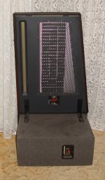
Examining the Apogee Duetta Signatures, I see the magnets are ceramic.
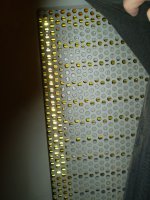
The tweeter is a true ribbon, with magnets approx 1.25" spaced and sized 2"x1"x0.5" approx and stacked in 2 layers on each side.
Anyone know how the Stage tweeter is constructed?
All I know is it is 0.7" wide and 26" long but I haven't seen one up close.
Thanks
Examining the Apogee Duetta Signatures, I see the magnets are ceramic.
The tweeter is a true ribbon, with magnets approx 1.25" spaced and sized 2"x1"x0.5" approx and stacked in 2 layers on each side.
Anyone know how the Stage tweeter is constructed?
All I know is it is 0.7" wide and 26" long but I haven't seen one up close.
Thanks
The magnets for the ribbons on mine measure 1 7/8" X 7/8" X 3/4".
They are the same size but twice the thickness of the ceramic magnets that I had stockpiled from Radio Shack many years ago.
They also seemed to have the same strength per thicknes as well.
I have also recently aquired some of the same material at a local hardware store that measure 1 7/8" X 7/16" X 3/8" rather cheap and I was thinking making a desktop scale model of the Duette's aswell using them.
But I would much rather use some Neo's for them as it would increase the eficeincy greatly as per size.
The Apogee's that I now have, Is what had inspired me to buy all of those magnets and I still have the two foot stack that I had super glued together for ribbon expriments.
I Wish I could get them apart so that I could utilize them for the bass panels ,But I haven't been able figure it out without damaging them yet.
If there is any thing else you need to know about them Mine are in sad shape and the covers are off of them, But they are rebuildible and I will refurbish them when I get the room to work on them someday.
They still work but the bass panels rattle and seem to have lost some of there tension.
I have the current Info on how to repair them but the issue is the amount of room I have to work on them right now.
Jer
Do you have the Stage Jer? I would like to see some images of them with the covers off.
Where did you get information on how to repair them?
I'd like to see that.
I did not take the covers off the Duetta so the magnet size is really approx.
I like your idea of building a desk top clone.
Thanks
Where did you get information on how to repair them?
I'd like to see that.
I did not take the covers off the Duetta so the magnet size is really approx.
I like your idea of building a desk top clone.
Thanks
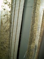
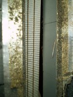
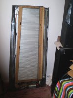
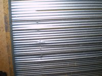
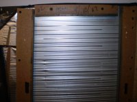
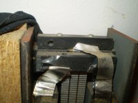
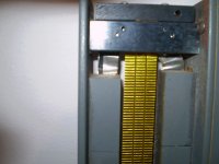
Here are some close ups of the ribbon and magnets, I tried to get an extreme closeup but the Focus was giving me a bad time!
But I can at a later time as I have a few ways to get almost to a microscopic level with it.
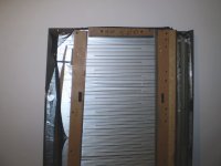
These are Duette's.
I got the info by doing some Digging and it was sent to me email from a fellow DIY'er earlier this year in a PDF via Email.
I will dig it up for you if you wish.
I hope these are of some help to you!
Enjoy, Jer
But I can at a later time as I have a few ways to get almost to a microscopic level with it.
These are Duette's.
I got the info by doing some Digging and it was sent to me email from a fellow DIY'er earlier this year in a PDF via Email.
I will dig it up for you if you wish.
I hope these are of some help to you!
Enjoy, Jer
Attachments
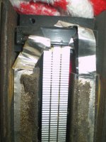
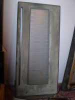
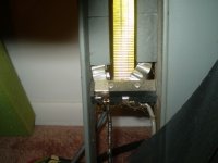
Here are some more pics and like I said before sad,sad, shape.
The magnetic circuit for the ribbon is open and there are No shorting bars at all anywhere in the structure.
the magnets are attached to 1/8" iron plate bars and the spacers are black plastic or phenolic or something.
I don't know if any glue was used or not as I haven't gotten into them very far yet.
Sorry the one picture that you wanted came out blurry but you can still make it out I would have taken another shot but my batteries died and I had to resort to an old an weak set in order to download the pics, Sorry.
I will try to get some more when I get a fresh charge on them.
Jer
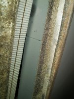
P.S I stand corrected ,There are 7 1/2" X 1/2" shorting bars on the back side of the ribbon structure spaced evenly along the length of the ribbon I will flip it over and get a picture for you.
The magnetic circuit for the ribbon is open and there are No shorting bars at all anywhere in the structure.
the magnets are attached to 1/8" iron plate bars and the spacers are black plastic or phenolic or something.
I don't know if any glue was used or not as I haven't gotten into them very far yet.
Sorry the one picture that you wanted came out blurry but you can still make it out I would have taken another shot but my batteries died and I had to resort to an old an weak set in order to download the pics, Sorry.
I will try to get some more when I get a fresh charge on them.
Jer
P.S I stand corrected ,There are 7 1/2" X 1/2" shorting bars on the back side of the ribbon structure spaced evenly along the length of the ribbon I will flip it over and get a picture for you.
Attachments
Last edited:
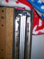
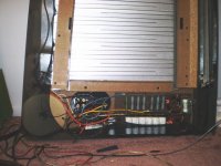
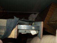
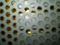
Here is the Backside of the Apogee Duette showing the magnet structure of the panel.
Note the seven shorting bars that I forgot that they were there! He,he
It is a very simple system ,But yet very Ingineous for the time I sure would like to hear a set of this made with some Neo's.
My biggest gripe and probably the only one was that it takes everybit of 1000watts or more to make them really sing nice .
Mine were originaly paired with some Aragon amps.
Unfortunatley those disappeared,Although I do still have the Aragon preamp for them.
I used a Crown DC300-A's on the ribbons and an Ashely FTX-2000 on the bass panels and it was just enough to make them sound decent but not exetremly loud but the clarity was unlike anything that I have ever heard before at that point in time.
Jer
Attachments

Great pictures.Are the shorting bars behind the tweeter ribbon?
How about the magnet structure for the woofer?
Sure is helpful, and finding the PDF would be sweet.
Not so much steel in it.
Why is the Duetta so heavy?
First of all, there is much steal and weight in the tweeter section. Believe me!
Next, the bass structure is so heavy You would not believe.
One person said that that's why they are so much better then Magneplanars from Magnepan. And that's so true.
You should know that the magnets themselves are quite heavy. Not to mention the very thick hole plate they are glued to.
If You try to knock on the hole plate in the back of the bass panel, it is totally dead and thus have NO resonance what so ever. That is VERY good indeed!
Try doing that on other planars. hehehe
Maybe will this give you an idea,
Tweeter section,
2 - 2" x 3/16" iron plate.
48 - 1 7/8" X 7/8" X 3/4" ceramic magnets.
7 - 2 3/4" X 3/4" X 1/2" steel support bars.
Woofer panel,
1 - 1' X 4' X 1/8" preforated steel panel.
123 magnets in a 41 X 3 arrangement.
Crossover,
1 - 6" dia. and 2 - 3" dia. all copper inducters plus capacitor,resistor and other hardware.
And enough wood for 2 1/2 layers of 2' X 5' X 3/4" MDF !
Not much but it all adds up.
jer
Last edited:
Yes, The shorting bars ar behind the ribbon.
I will Find the PDF for you.
jer
I found another link of some dissassembled ones while doing some more digging, Enjoy !!!
http://picasaweb.google.com/jerker.lindborg
I will Find the PDF for you.
jer
I found another link of some dissassembled ones while doing some more digging, Enjoy !!!
http://picasaweb.google.com/jerker.lindborg
Last edited:
Here is the link as it is in german but I ran it through Googles translator and it worked okay.
http://www.dis-magnetostaten.de/forum/manual.pdf
jer
http://www.dis-magnetostaten.de/forum/manual.pdf
jer
The Apogee's that I now have, Is what had inspired me to buy all of those magnets and I still have the two foot stack that I had super glued together for ribbon expriments.
I Wish I could get them apart so that I could utilize them for the bass panels ,But I haven't been able figure it out without damaging them yet.
Have you tried this: Removing Super Glue | Super Glue Corporation
Thanks, I had forgot about using acetone next time I get a new can I will try it.
I have been meaning too do it in the past but the concept never occured at the same time as when I had some acetone.
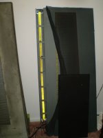
It is two very large stacks about 2 feet long and each stack is 5 or 6 layres deep ,glued to some 3/4" particle board,so it is not going to be easy by any means.
I had just recently relocated it in my huge pile of stuff this last summer.
I made it sometime in the mid 90's and it is still intact.
I will post a picture of it soon.
Thanks! jer
I have been meaning too do it in the past but the concept never occured at the same time as when I had some acetone.
It is two very large stacks about 2 feet long and each stack is 5 or 6 layres deep ,glued to some 3/4" particle board,so it is not going to be easy by any means.
I had just recently relocated it in my huge pile of stuff this last summer.
I made it sometime in the mid 90's and it is still intact.
I will post a picture of it soon.
Thanks! jer
Here are some close ups of the ribbon and magnets, I tried to get an extreme closeup but the Focus was giving me a bad time!
But I can at a later time as I have a few ways to get almost to a microscopic level with it.
These are Duette's.
I got the info by doing some Digging and it was sent to me email from a fellow DIY'er earlier this year in a PDF via Email.
I will dig it up for you if you wish.
I hope these are of some help to you!
Enjoy, Jer
Interesting to note ! ..
The returns are run outside the field, something I have suggested on here many times before. Most of the builds here have the return running in the field , it is the wrong way of doing it ...
No,I am not going to redo the frames,
I just want to some how retension the woofer section if I can as they have a slight rattle.
I don't want to damage the original Diagphram or have to try to replace it.
Trying to locate just a 12' X 18" X 1mil piece kapton may prove to be very hard to acomplish not to mention the cost.
I have some 1" and 3" or 4" stuff and it is an extremely durable material.
It has been said that their edges are suspended by foam and all of the foam that exsisted has now withered away.
Unfortunately there is no easy way to get to the backside so that I can reform the creases and redo the edges.
Inorder to do this I may have to cut the MDF frame inorder to lift out the magnet structure and then remount the two pieces on a new backing piece.
I am not quite sure yet on the process I will choose yet,But it might be the only way to go as I really don't want disturb the diagphram and its mounting frame and geometery as it is not that badly damaged yet and still works.
Also when I first got them home I didn't have them properly setup and they were just leaning against the wall.
And the extra backwave preasure could have been the cause of the rattling as well as from being overdriven abit much as they are 14 feet from my listening position and suffered greatly from dipole cancelation in this configuration.
There as also the possibility that there may not be anything wrong with them because the amp ( an Ashely FTX-2000 ) started to devolep some probelms and eventualy quit working on my main stack of speakers and that was when I had to switch everything over to my Crown DC300a.
a.wayne,
I agree, The returns should be run outside of the magnetic field as to not modulate the field even as slight as it may be, Also I believe that some form dampening may occur to the signal as well if it is routed within the field.
The returns on the ribbons are run along the tops of the magnets on their centers, Although they are not directly in the magnetic circuit, IMHO I think that it is still to close for comfort and that it is just heavy gauge aluminium tape stuck directly to the magnet with no insulating material between the conductor and magnet assembly.
I find this to be a pis poor design although it has been working since 1987 when they were built.
Any Thoughts? jer
Last edited:
Currently mine are built very similar to the apps,(frames) just direct, (similar to there fullrange unit) no returns at all , wire wound vishay resistors on heat sinks are used to a bare minimum, for 1.2 ohm loading mid/twt and they are coupled to a 4 ohm dynamic bass driver -3 db down at 38 hz..
Drives the amps batty , but the sound is ......


Drives the amps batty , but the sound is ......
- Home
- Loudspeakers
- Planars & Exotics
- Apogee Speakers Construction