How best to wire-up and ground the EMCO f-series which are not center-tapped?
A center-tapped module would only be needed if you require two polarities of HV, such as if you were building a FINAL style "inverted" ESL where you put equal but opposite HV bias on the two stators, or a double diaphragm triple stator affair where diaphragms have equal but opposite HV bias.
For typical constant charge ESLs, simply connect the (-)Output of the EMCO f-series to your step-up transformer center tap and the (+)Output to the diaphragm thru an appropriate high value charge resistor. If you prefer a negative charge on your diaphragm, swap the (-) & (+) outputs.
The specs state that the CCFL's are AC output...They just use a couple of transistors in a multivibrator configuration to drive the transformer. I don't recall any regulation built in to it either, there may have been a zener diode but I don't remember...I had found this odd for a constant voltage output type.
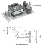
CCFL inverters are a resonant version of the Royer oscillator circuit dating back to the 50s. The original Royer circuit used transformer saturation to drive the switching and output square waveform like a mulitvibrator. The CCFL inverters however are designed with a tuned circuit on the primary side and put out a nice clean sinewave with very little harmonic content radiated. The circuit for non-dimming version looks surprisingly simple, although as you can imagine the special transformer is a big part of what makes that possible. Attached circuit is for the TDK modules that you can pick up for around $10.
More info here==>http://www.diyaudio.com/forums/plan...nel-efficiency-first-build-9.html#post3471237
Regarding regulation: This type of circuit has surprisingly good self regulation. For a given DC input voltage, the AC output voltage doesn't vary much at all with different loads. Also the magnitude of the output voltage varies linearly with the DC input voltage. Obviously if you feel the need to improve regulation, it is easy enough to feedback a rectified/smoothed portion of the output voltage to an LM317 used to regulate the DC input voltage. I have not found this to be necessary.
For ESL use, all you need to do is remove the small capacitor used for current regulation when driving a CCFL(lamp) and wire in a few voltage multiplier sections with appropriately rated diodes and caps. The inverter usually run in the 20Khz - 50Khz range, so the filter capacitors don't need to be nearly as high in value as for the usual 60Hz multipliers.
To give you an idea, Martin Logan uses 470pF smoothing caps in their more recent HV supplies that use a CCFL type inverter.
Attachments
Last edited:
A center-tapped module would only be needed if you require two polarities of HV, such as if you were building a FINAL style "inverted" ESL where you put equal but opposite HV bias on the two stators, or a double diaphragm triple stator affair where diaphragms have equal but opposite HV bias.
For typical constant charge ESLs, simply connect the (-)Output of the EMCO f-series to your step-up transformer center tap and the (+)Output to the diaphragm thru an appropriate high value charge resistor. If you prefer a negative charge on your diaphragm, swap the (-) & (+) outputs.
Thanks for answers. I was dreaming about grounding "in the middle" for safety reasons.
Some of my step-up matching transformers have no center-tap on the HV side. I suppose connecting the EMCO low voltage (and grounded) tap with big resistors to each end (connected to the stators) would work fine (and with the EMCO HV end to the membrane), for safety reasons.
Ben
Thanks Bolserst, That is the one !!!
That is the schematic I had found!!!
It is not found on the common PDF data sheet but it was on the one I had found, Once !!!
Thanks for the info on being able to vari it, I had suspected that it would work!!
That would be a drop in replacement to HV generation section in my regulated Variable HV Bias supply.
The problem with the EMCO and some CCFL's is its higher voltage output would require a very high voltage diode or a string of 1KV to 2Kv ones in series in which is not to much of a problem if it has a AC output.
But it is not very cost effective when you add up the > 8-10Kv worth of capacitors required to filter the output.
I have already done the math on this and as I had mentioned parts with > 2Kv ratings start to get very costly and sometimes hard to source.
I have found a huge jump in the price of diodes just going 1500v-1600v to 2000v, Huge jump from about $.25-$.75 to $2-$4 a piece!!!
And they must be fast types to boot!!
Although, The EMCO module looks nice as it already does have a DC output.")
Still in the long run I think that it can be a cheaper way to go considering the cost of even small transformers these days.
The Cores that I used in my power supply were just some common mode filter chokes found in old PC switchers and such.
Cheers!!
jer
That is the schematic I had found!!!
It is not found on the common PDF data sheet but it was on the one I had found, Once !!!
Thanks for the info on being able to vari it, I had suspected that it would work!!
That would be a drop in replacement to HV generation section in my regulated Variable HV Bias supply.
The problem with the EMCO and some CCFL's is its higher voltage output would require a very high voltage diode or a string of 1KV to 2Kv ones in series in which is not to much of a problem if it has a AC output.
But it is not very cost effective when you add up the > 8-10Kv worth of capacitors required to filter the output.
I have already done the math on this and as I had mentioned parts with > 2Kv ratings start to get very costly and sometimes hard to source.
I have found a huge jump in the price of diodes just going 1500v-1600v to 2000v, Huge jump from about $.25-$.75 to $2-$4 a piece!!!
And they must be fast types to boot!!
Although, The EMCO module looks nice as it already does have a DC output.
Still in the long run I think that it can be a cheaper way to go considering the cost of even small transformers these days.
The Cores that I used in my power supply were just some common mode filter chokes found in old PC switchers and such.
Cheers!!
jer
Last edited:
Interesting... Do you have a full picture of that Martin Logan HV CCFL type inverter?CCFL inverters are a resonant version of the Royer oscillator circuit dating back to the 50s. The original Royer circuit used transformer saturation to drive the switching and output square waveform like a mulitvibrator. The CCFL inverters however are designed with a tuned circuit on the primary side and put out a nice clean sinewave with very little harmonic content radiated. The circuit for non-dimming version looks surprisingly simple, although as you can imagine the special transformer is a big part of what makes that possible. Attached circuit is for the TDK modules that you can pick up for around $10.
More info here==>http://www.diyaudio.com/forums/plan...nel-efficiency-first-build-9.html#post3471237
Regarding regulation: This type of circuit has surprisingly good self regulation. For a given DC input voltage, the AC output voltage doesn't vary much at all with different loads. Also the magnitude of the output voltage varies linearly with the DC input voltage. Obviously if you feel the need to improve regulation, it is easy enough to feedback a rectified/smoothed portion of the output voltage to an LM317 used to regulate the DC input voltage. I have not found this to be necessary.
For ESL use, all you need to do is remove the small capacitor used for current regulation when driving a CCFL(lamp) and wire in a few voltage multiplier sections with appropriately rated diodes and caps. The inverter usually run in the 20Khz - 50Khz range, so the filter capacitors don't need to be nearly as high in value as for the usual 60Hz multipliers.
To give you an idea, Martin Logan uses 470pF smoothing caps in their more recent HV supplies that use a CCFL type inverter.
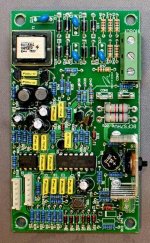
Also can someone tell me what's the purpose of this diode ground loop circuit on D12, D13, Z3, Z4, Z5, Z6, Z7, Z8 Z9, Z9, Z10, Z11, Z12, Z13, D26, D27 in this Martin Logan HV bias board schematic? Is this to filter the transformer AC transient voltage or interference from the HV DC full wave multiplier section? I noticed the amount of Z3 thru Z13 diodes and jumpers can be altered with different models.
.
Attachments
I can post a picture next week of the full board, but what you see is all there is to the HV CFFL type supply. The rest of the board contains auto ON/OFF and MOSFET Limiter clamps to keep from arcing the panel if overdriven.Interesting... Do you have a full picture of that Martin Logan HV CCFL type inverter?
Also can someone tell me what's the purpose of this diode ground loop circuit on D12, D13, Z3, Z4, Z5, Z6, Z7, Z8 Z9, Z9, Z10, Z11, Z12, Z13, D26, D27 in this Martin Logan HV bias board schematic?
Martin Logan uses a string of zener diodes(Z3 - Z12) inside of a bridge rectifier(D12,13, D26,27) to regulate the output of the bias supply transformer which is fed to the HV multiplier. So, varying AC wall voltage does not affect the HV bias voltage.
http://www.diyaudio.com/forums/planars-exotics/200227-martinlogan-bias-mod-2.html#post2822763
Last edited:
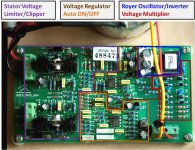
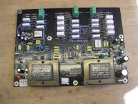
I just happened to locate a picture of the newer version power supply on another forum for the Summit-X.
Thanks for pic of the Summit-X power supply board.
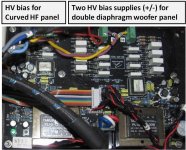
Here are two other ML power supply boards that use the Royer style oscillator/inverter.
I marked the functional zones on the Spire board since I am familiar with it.
Two interesting things I noticed on the CLX board:
1) Separate inverters were used; one for the lower bias voltage of the curved HF panel,
and another for the higher bias voltage of the double diaphragm woofer.
2) In the two voltage multipliers for the woofer panel(+HV for one diaphragm, -HV for the other) it appears they used larger capacitors for 4 out of 8 caps in the multiplier chain.
I've seen HV supplies where the first capacitor in the multiplier chain was increased in size to substantially reduce ripple at minimal cost, but increasing size of half the caps is new to me...not sure what the reasoning is. Considering the cost of the CLX, if ripple reduction was the goal why didn't they just use the larger value for all 8 caps? Thoughts anybody?
Credits:
Spire HV board pic courtesy of Paul S
CLX HV board pic courtesy of ticknpop
Attachments
The CLX dual force woofer panel uses a double diaphragm and three stators for each low frequency transducer. I'm guessing that full wave rectifier high voltage multiplier has the larger capacitors on the positive AC wave form and on the opposite for the negative side. Maybe this limits the diaphragm movement in one direction for tighter bass response with improved dipole phase stabilization. It also appears to have more diodes on the one side but it would be very interesting if someone could locate a schematic for this HV supply.

IF you folks still want an adjustable HV supply, I designed one that worked very well for me for years:
http://quadesl.com/speaker/diyesl/hv_supply.pdf
Sheldon
http://quadesl.com/speaker/diyesl/hv_supply.pdf
Sheldon
IF you folks still want an adjustable HV supply, I designed one that worked very well for me for years:
http://quadesl.com/speaker/diyesl/hv_supply.pdf
Sheldon
thx looks pretty nice
The standard voltage multiplier using 2 strings of capacitors is a half wave series multiplier.…I'm guessing that full wave rectifier high voltage multiplier has the larger capacitors on the positive AC wave form and on the opposite for the negative side… It also appears to have more diodes on the one side
A full-wave multiplier requires a transformer with center tapped secondary and 3 strings of capacitors.
Voltage Multipliers, Inc. - Types of High Voltage Multiplier Configurations
Concerning the extra diodes…I think all they are doing is putting two diodes in series for each rectifier block to halve the peak voltages seen by the diodes. For an example, so the schematic linked to in post#51.
http://www.diyaudio.com/forums/planars-exotics/190716-esl-power-supply-question-6.html#post3744943
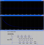
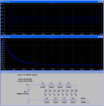
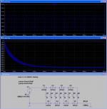
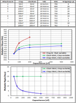
As usual curiosity got the better of me and after a bit of experimenting on the test bench, there actually appears to be a very good reason for only increasing half of the caps in the multiplier. Looking at the example multiplier circuit shown in the attachments, let’s call the upper string of capacitors Ctop, and the bottom string of capacitors Cbot. The long term ripple is determined only by the size of the Cbot caps. The Ctop caps only affect the long term DC voltage magnitude and how quickly it gets there.I've seen HV supplies where the first capacitor in the multiplier chain was increased in size to substantially reduce ripple at minimal cost, but increasing size of half the caps is new to me...not sure what the reasoning is.
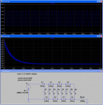
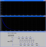
Rather than trying to tabulate and plot all my experimental results, I performed a few quick LTSpice runs to better illustrate the trends.
Attachment #1 Summary of Ctop, Cbot, Load, and Voltages for each run along with associated attachment pic.
Attachment #2 - 9 LTSpice screen captures for each run.
(Input voltage for each run was 100Vp = 70.71Vrms)
Some observations:
1) With a very light loading(10 Gohm) the output voltage is essentially Vp x number of capacitors. Voltage drops across diode junctions make it slightly less.
2) Every doubling of Cbot results in halving the ripple magnitude. Looking at the trend curve for ripple voltage at the bottom of Attachment #1 you can see that you may quickly ran into diminishing returns.
3) Increasing Ctop has no effect on ripple, but does increase the Vdc output. However, it would be just as easy to leave Ctop the same size and increase the input voltage to the multiplier by a small amount. I'm guessing this is the route that was chosen for the CLX woofer supplies.
Attachments
-
 HVmult_Ctop-50nF_Cbot-200nF_R-10M.png210.2 KB · Views: 76
 -
 HVmult_Ctop-50nF_Cbot-100nF_R-10M.png213.8 KB · Views: 69
 -
 HVmult_Ctop-200nF_Cbot-50nF_R-10M.png226.2 KB · Views: 226
 -
 HVmult_Ctop-100nF_Cbot-50nF_R-10M.png235.4 KB · Views: 239
 -
 HVmult_Ctop-50nF_Cbot-50nF_R-10M.png232.2 KB · Views: 242
 -
 HVmult_Ctop-50nF_Cbot-50nF_R-10G.png192 KB · Views: 242
 -
 HVmult_summary.png275.5 KB · Views: 246
Last edited:
Increasing the values of the caps also increase the output current capability of the multiplier stage as does increasing the input frequency.
I had found a few really excellent online calculators that take all of these factor in to detail.
I may have posted those links back in 2010 or I may not have, I will search for them later.
The one I liked in particular, you are able to adjust the input frequency and it would tell you the size of the caps to use and however many stages to use as per voltage and current output requirement.
It was fairly accurate as to the performance of my Variable HV supply and is what I used to plan it out.
jer
The Martin Logan Stage uses a single inverter for power supply with 470 pf ceramic 6 kv caps. The ML Request used polyester caps as does the CLX in the HV doubler. A friends low cost ML uses a wall wart supply and ceramic caps in the step up. The diodes in the CLX low and frequency supplies are the same 1 amp 1 kv soft recovery types, while the Stage and Request used 1n4007.
Increasing the values of the caps also increase the output current capability of the multiplier stage as does increasing the input frequency. I had found a few really excellent online calculators that take all of these factor in to detail.
Absolutely, ripple is inversely proportional to frequency as well.
Fortunately a properly operating ESL does not require much current capability.
I believe, all the calculators are based on formulas summarized(in grey boxes) on the Blazelabs page:
Experiments: Experiment 15
Calculations based on these equations certainly provide good guidance when deciding on frequency, number of stages, and capacitor size for your HV supply. Note that formulas are valid only for even number of multiplier capacitors/diodes with all caps of the same value. This point isn't particularly clear in the documentation.
@ticknpop
Thanks again for sharing details and pics of your ML products. Always new things to learn.
Last edited:
Yes, I believe that is one of the calculator's looks like they have added some color to it !!!
http://blazelabs.com/cw-brm-java.asp
jer
http://blazelabs.com/cw-brm-java.asp
jer
I find it interesting that ML use film caps in the doublers of their higher end products and cheaper, smaller ceramic caps in their smaller, cheaper speakers.
i used Wima 2000V FKP caps in updating my Stage's step up caps and when I update the CLX's with Duelands for the crossover resistors I will also change the CLX's polyester step up caps to film and foil 2kv Wima FKP's.
i have Quad 63, Dayton Wrights, Acoustats and all used ceramic caps for the step-up multipliers
- Status
- This old topic is closed. If you want to reopen this topic, contact a moderator using the "Report Post" button.
- Home
- Loudspeakers
- Planars & Exotics
- ESL Power supply question?