Trying to find history of my Acoustat Tube Amps
Greetings
I'm a new member to this forum and joined because this is one of the only places I found that discusses Acoustat products.
I've owned a pair of 2+2's and Acoustat "servo amps" since 1985.
I'm trying to understand the history of my amps, without reading thru 262 pages of posts") .
.
My Amps are marked Acoustat Model X, Serial # 1691 and 1692. When I originally got them they had oil filled coupling caps that went straight to the panels. From what I understand, they were not stock models, they had been modified by David Curcio. From what I could see, that had separate regulators for the Screen suppy of the 6HB5's and a reguator for the B+ of the 6DJ8 drivers.
In the early '80's I became friends with Danny Fanny (founder of American Hybrid Technology...now defunct) and he made some additional mods...changed some components, most notably got rid of the oil filled caps and replaced with polystyrene caps or polypropylene..not sure, and most recently, just before the pandemic hit, some additional mods. Mainly replacing the caps and resistors in the signal path.
I also understand from reading here there are also "Medallion Transformers" to drive the Panels. Are these a stand alone interface to bias panels? Do they also have an Acoustat Tube amp that drives that interface? Do you supply your own conventional amp (either valve or solid state)?
What came first, the Transformer or my Servo Amps?
TIA for any answers.
ps..I am totally happy with this system, I do have it set up in a Dead End, Live
End type of room and it is a pleasure to listen to.
Greetings
I'm a new member to this forum and joined because this is one of the only places I found that discusses Acoustat products.
I've owned a pair of 2+2's and Acoustat "servo amps" since 1985.
I'm trying to understand the history of my amps, without reading thru 262 pages of posts
.My Amps are marked Acoustat Model X, Serial # 1691 and 1692. When I originally got them they had oil filled coupling caps that went straight to the panels. From what I understand, they were not stock models, they had been modified by David Curcio. From what I could see, that had separate regulators for the Screen suppy of the 6HB5's and a reguator for the B+ of the 6DJ8 drivers.
In the early '80's I became friends with Danny Fanny (founder of American Hybrid Technology...now defunct) and he made some additional mods...changed some components, most notably got rid of the oil filled caps and replaced with polystyrene caps or polypropylene..not sure, and most recently, just before the pandemic hit, some additional mods. Mainly replacing the caps and resistors in the signal path.
I also understand from reading here there are also "Medallion Transformers" to drive the Panels. Are these a stand alone interface to bias panels? Do they also have an Acoustat Tube amp that drives that interface? Do you supply your own conventional amp (either valve or solid state)?
What came first, the Transformer or my Servo Amps?
TIA for any answers.
ps..I am totally happy with this system, I do have it set up in a Dead End, Live
End type of room and it is a pleasure to listen to.
Last edited:
Quick question: in a 1+1, if a top panel is making a rattling sound, would that indicate a panel issue or an interface one (transformer)?
Does the top panel handle only highs (by one transformer) or are both fully driven?
all panels run full range. if a panel rattles it has a problem could be the panel is loose could be that some of the stator panels have broken loose could be the diaphragm has lost tension and is fluttering can make a lot of noise. You are going to have to take them apart and have a very detailed look and come back when you have something to report.
Greetings
I'm a new member to this forum and joined because this is one of the only places I found that discusses Acoustat products.
I've owned a pair of 2+2's and Acoustat "servo amps" since 1985.
I'm trying to understand the history of my amps, without reading thru 262 pages of posts
My Amps are marked Acoustat Model X, Serial # 1691 and 1692. When I originally got them they had oil filled coupling caps that went straight to the panels. From what I understand, they were not stock models, they had been modified by David Curcio. From what I could see, that had separate regulators for the Screen suppy of the 6HB5's and a reguator for the B+ of the 6DJ8 drivers.
In the early '80's I became friends with Danny Fanny (founder of American Hybrid Technology...now defunct) and he made some additional mods...changed some components, most notably got rid of the oil filled caps and replaced with polystyrene caps or polypropylene..not sure, and most recently, just before the pandemic hit, some additional mods. Mainly replacing the caps and resistors in the signal path.
I also understand from reading here there are also "Medallion Transformers" to drive the Panels. Are these a stand alone interface to bias panels? Do they also have an Acoustat Tube amp that drives that interface? Do you supply your own conventional amp (either valve or solid state)?
What came first, the Transformer or my Servo Amps?
TIA for any answers.
ps..I am totally happy with this system, I do have it set up in a Dead End, Live
End type of room and it is a pleasure to listen to.
The amps are from the first Acoustat speaker, the X. The next generation of speakers, the Monitor 3 and 4 also had direct drive tube amps. All. subsequent generations used transformers where the user supplied an amp of their choosing.
Someone replaced the transformers with the amps from an X, Monitor 3 or 4.
Cheers,
OldMovieNut
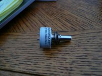
Wondering if anyone can advise on power rating for volume and tone pots on the DD Servo OTLs. They're a bit scratchy and I want to replace them. Right now they are 1watt pots. Available quality upgrades are quite a bit lower in rating, like typically 1/4watt. How critical is it? TIA
Hi, I have made some ?progress? on my Spectra 11's that I had posted about over on #2460
I did the power supply update which did bring the bias up a bit but not enough. one of the speakers will get up to a bias of roughly 44v the other to about 62v. I have tried many things. I replaced the input diodes, the diodes on the HV side, the transistor, replaced the zener diode with a 13v, I did the update and checked all of the other components on the board to see if they are within spec, swapped the wall warts from speaker to speaker. I feel like I am running out of options.
The only components that I haven't checked are the high volt ceramic caps, the large 500m resistor on the high volt side, the ceramic caps, the 10m resistor that the grey wires go to ground from. I even pulled off the trimmers and checked if they were good.
From what I understand, ceramic caps rarely go out. I have a LCR meter and may pull a couple off and see what the ESR is on them. Can I pull them out of the circuit and see if that changes the bias? Also, is it worth it to try to change the large 500m resistor?
I noticed that the voltages are higher on the low volt side of the power supply that has the lower bias. I can only assume that is because the little wall wart transformer doesn't have enough of a load on it to pull the voltage down.
I may try cleaning the ground wire connection to see if that helps before I go digging into the power supply further than I already have. If I can figure out this issue, the interface will pretty much stuffed with all new parts throughout!
Try some Nu-trol control spray cleaner for the pots. Give them a shot of the cleaner in the openings where the 3 terminals are. Power off of course;^)Wondering if anyone can advise on power rating for volume and tone pots on the DD Servo OTLs. They're a bit scratchy and I want to replace them. Right now they are 1watt pots. Available quality upgrades are quite a bit lower in rating, like typically 1/4watt. How critical is it? TIA
thanks. I have deoxit but these are now 40 years old. I bought some new ones. I have 3 pairs of these amps and I'm noticing they vary in the action of the pots in that one may feel smooth while another feels like a spike digging and dragging as I turn it. Time to change them
These are very nice with great specs
These are very nice with great specs
Attachments
Hi, I have made some ?progress? on my Spectra 11's that I had posted about over on #2460
I did the power supply update which did bring the bias up a bit but not enough. one of the speakers will get up to a bias of roughly 44v the other to about 62v. I have tried many things. I replaced the input diodes, the diodes on the HV side, the transistor, replaced the zener diode with a 13v, I did the update and checked all of the other components on the board to see if they are within spec, swapped the wall warts from speaker to speaker. I feel like I am running out of options.
The only components that I haven't checked are the high volt ceramic caps, the large 500m resistor on the high volt side, the ceramic caps, the 10m resistor that the grey wires go to ground from. I even pulled off the trimmers and checked if they were good.
From what I understand, ceramic caps rarely go out. I have a LCR meter and may pull a couple off and see what the ESR is on them. Can I pull them out of the circuit and see if that changes the bias? Also, is it worth it to try to change the large 500m resistor?
I noticed that the voltages are higher on the low volt side of the power supply that has the lower bias. I can only assume that is because the little wall wart transformer doesn't have enough of a load on it to pull the voltage down.
I may try cleaning the ground wire connection to see if that helps before I go digging into the power supply further than I already have. If I can figure out this issue, the interface will pretty much stuffed with all new parts throughout!
Are you measuring the bias voltage with speaker disconnected? If not, and one of the panels has a bias leak, it could be pulling down the bias.
My next suspicion would be the capacitors in the high voltage multiplier. These are pretty reliable, but your speaker is already 30-ish years old, and at this point, one must be suspicious of all components. Be sure to replace all of them at once, using the same type, capacitance and voltage value. Here's a recommended replacement diode and capacitor:
Vishay GP02-40 diode, 250 mA, 4000 volts
Mouser p/n 625-GP02-40-E3
Vishay 564R30TSD33 capacitor, 3300 pF, 3000 volts
Mouser p/n 75-564R30TSD33
My next step would be the 500M-ohm resistor. You can't measure its value with a conventional ohmmeter, so you could try swapping parts between interfaces as a troubleshooting step.
Any fault in the 10M-ohm resistor should should not affect your bias readings.
Good luck!
Thank you for your reply. I was testing both with the panels disconnected and then with the panels connected (letting the interface run for 24hrs)
I have already replaced the HV diodes and will go ahead and try the HV multiplier caps next.
Also, do you have a good recommendation for replacing the 500m resistor?
Thanks for your reply!
Mike
I have already replaced the HV diodes and will go ahead and try the HV multiplier caps next.
Also, do you have a good recommendation for replacing the 500m resistor?
Thanks for your reply!
Mike
What is the purpose of the single wire that comes out of the same side as the primary wires of the transformers which is sandwiched between the transformer's frame laminations and its mounting bracket? It's white on high frequency Medallions and black on the old high frequency transformers. Thanks!
Do you think this resistor will work or is 1.4W not enough?
https://www.mouser.com/ProductDetail/Ohmite/MOX1125225006KE/?qs=vOeJqewp7jC9UUjbVkMEHA==
https://www.mouser.com/ProductDetail/Ohmite/MOX1125225006KE/?qs=vOeJqewp7jC9UUjbVkMEHA==
What is the purpose of the single wire that comes out of the same side as the primary wires of the transformers which is sandwiched between the transformer's frame laminations and its mounting bracket? It's white on high frequency Medallions and black on the old high frequency transformers. Thanks!
Based on memory, I believe those are ground wires. Aren't they the ones that go to the ground connection on the PC board?
Based on memory, I believe those are ground wires. Aren't they the ones that go to the ground connection on the PC board?
No, the ones that go to the board come out in the same area that the blue and yellow ones that go to the board come out. This wire comes out of the transfomer all by itself on the primary side, but opposite to where the black and red primary wires exit. It ends sandwiched between the mounting bracket of the transformer and its laminations. So they do get grounded by virtue of the metal to metal mounting to the interface case through the transformer mounting screws. I couldn't get any measurable resistance between the wire and any winding wire of the transformer, primary or secondary.
Please understand that I have forgotten more about Acoustat than I currently remember - a result of 30 years absence. Now that I think about it (and your alternate description helps) I seem to recall these are electrostatic shields that get grounded to the frame of the transformer. Being shields, you won't (or shouldn't!) get any continuity from the shield to any of the windings. Being an internal part of the transformer, I never gave them much thought.
Perhaps someone with more ESL transformer knowledge can chime in here, regarding physical placement of the shield relative to the windings, and the advantages of including such a feature.
Perhaps someone with more ESL transformer knowledge can chime in here, regarding physical placement of the shield relative to the windings, and the advantages of including such a feature.
Thanks for even taking my question on. I realize it's a pretty esoteric one. I keep thinking about someone on a different board going on about "star grounding" and I can't find many applications of it in these interfaces. This may be one of them? The only other star grounding candidate that I can see would be taking the secondaries' white wires and the bias transformer output ground to the single ground point at the bias transformer mounting screw that goes to the green ground wire that goes to the IEC power socket.
Found this on the Hammond website: "Electrostatically shielded (Faraday Shield) transformers provides a copper electrostatic shield between the primary and secondary windings. The shield is grounded and thus shunts some noise and transients to the ground path rather than passing them through to the secondary. Transformers having a K-Rating are required to have an electrostatic shield.
Electrostatically shielded transformers often preferred for electrical installations where electronic circuitry operating at low voltage DC is present and is very sensitive to ‘noise’. Recent testing of electrostatically shielded transformers has questioned their perceived effectiveness where the transformer’s secondary is grounded which would cover most applications."
So it may not have any useful effect in this application.
Thanks for even taking my question on. I realize it's a pretty esoteric one. I keep thinking about someone on a different board going on about "star grounding" and I can't find many applications of it in these interfaces. This may be one of them? The only other star grounding candidate that I can see would be taking the secondaries' white wires and the bias transformer output ground to the single ground point at the bias transformer mounting screw that goes to the green ground wire that goes to the IEC power socket.
I don't think the advantages of star-grounding apply here, nor would I recommend any changes to the current grounding scheme. Which model interface are you talking about here?
These are MK-121 interfaces from 1980-1981 Model 3s and 4s, upgraded to C and Medallion spec. I can see star grounding being better because if the chassis is used as ground, ground return currents can take random paths through the metal case and cause random noise generation as a result. Star grounding gives well defined narrow paths that don't change. I could see possible bleed of this random noise from one transformer's ground into the other's electrostatic shield also, but I may be chasing ghosts that don't exist.
- Home
- Loudspeakers
- Planars & Exotics
- Acoustat Answer Man is here