Acoustat Servo Resistors and capacitors tackle box
Not sure if anyone can use this, but it has a lot of parts:
Acoustat Servo Resistors and capacitors tackle box | eBay
Not sure if anyone can use this, but it has a lot of parts:
Acoustat Servo Resistors and capacitors tackle box | eBay
Improvements to Spectra Interfaces
In the AudioCircuit someone inquired about improving/upgrading the Spectra (Mk2123) interfaces. I believe the upgrade was above and beyond replacing caps or resistors. In the thread, Roy Esposito who used to work at Acoustat in Florida and still does repair work on Acoustat products responded with the following "You are sadly mistaken about the MK2123 Rockford iterations being oh-so-perfect and not in need of corrections or service. The designed-in distortion is measurable. And curable. You have also been mistaken in the past praising Acoustat/Rockford\'s Ultrasonic Bias Supply, over the original Bias system used in many of the later interfaces".
Would anybody know what the issues are with the Spectra interfaces and what improvements can be made as I am working on my interfaces at this time during the quarantine. I hope you are all well and thank you for any input.
Regards,
gwho
It is most likely a loose stator wire with a number of broken glue points in a row. You can track it down by pulling down the sock and carefully checking the glue points on the louvers. When you find them, carefully put a dab of model glue on each one. Keep the speaker upright to prevent glue from dropping accidentally on the mylar.I have a pair of model 3s. Once in a while I cn hear a buzzing in one speaker. It's very slight but definitely there. Are there any suggestions on how to diagnose?
Last edited:
Why don't you get a hold of Roy?In the AudioCircuit someone inquired about improving/upgrading the Spectra (Mk2123) interfaces. I believe the upgrade was above and beyond replacing caps or resistors. In the thread, Roy Esposito who used to work at Acoustat in Florida and still does repair work on Acoustat products responded with the following "You are sadly mistaken about the MK2123 Rockford iterations being oh-so-perfect and not in need of corrections or service. The designed-in distortion is measurable. And curable. You have also been mistaken in the past praising Acoustat/Rockford\'s Ultrasonic Bias Supply, over the original Bias system used in many of the later interfaces".
Would anybody know what the issues are with the Spectra interfaces and what improvements can be made as I am working on my interfaces at this time during the quarantine. I hope you are all well and thank you for any input.
Regards,
gwho
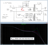
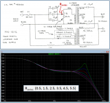
The main effect of the HF pot setting is to adjust the amount of resistance in series with the HF transformer primary. This effectively adjusts damping of the HF resonance between the transformer leakage inductance and panel capacitance which defines the upper bandwidth limit. Since the MK121 and MK121C interfaces have similar HF transformers, response trends for the same amount of series resistance are similar.…I was hoping to see the frequency response curves at different settings of the hi freq pot.
In the attached response trends, the portion of the resistor in series with the primary was adjusted from 0.5ohm to 5.5 ohm in steps of 1.0 ohm. The other portion of the resistor was also adjusted appropriately to keep the total resistance constant. (ie 6ohm for MK121, and 16ohm for MK121C)
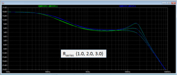
The last plot is an overlay of the MK121 and MK121C for series resistance of 1, 2, & 3 ohm.
You can see the HF response trend is nearly identical.
Attachments
The main effect of the HF pot setting is to adjust the amount of resistance in series with the HF transformer primary. This effectively adjusts damping of the HF resonance between the transformer leakage inductance and panel capacitance which defines the upper bandwidth limit. Since the MK121 and MK121C interfaces have similar HF transformers, response trends for the same amount of series resistance are similar.
In the attached response trends, the portion of the resistor in series with the primary was adjusted from 0.5ohm to 5.5 ohm in steps of 1.0 ohm. The other portion of the resistor was also adjusted appropriately to keep the total resistance constant. (ie 6ohm for MK121, and 16ohm for MK121C)
The last plot is an overlay of the MK121 and MK121C for series resistance of 1, 2, & 3 ohm.
You can see the HF response trend is nearly identical.
I did the "C" mod to my MK121 interfaces using a 10ohm resistor and keeping the variable pot. Where should that be setting? I have it at the noon (12 o'clock) position. The manual says use it at the 3 o'clock position, but that was with a stock MK121 . Thanks!
I did the "C" mod to my MK121 interfaces using a 10ohm resistor and keeping the variable pot. Where should that be setting? I have it at the noon (12 o'clock) position. The manual says use it at the 3 o'clock position, but that was with a stock MK121 . Thanks!
It's a variable control for a reason - so you can adjust it to suit your tastes. Therefore, there is no "correct" position - adjust it the way that sounds the best to you. Depending on the interface, the adjustment may be of the rotary type, or the linear slider type. Same comments apply to all versions of the 121, 131 and 141 interface series.
Thanks for the plots bolserst. I think I expected more difference between the two circuit designs. The higher low frequency content of the MK-121 version I would guess is due to the direct non-capacitive path through the pot that doesn't exist in the C version.
I'm surprised at the Q when the pot is near the extreme high end. Looks like if you want flat as possible, around 3.3 ohms is the spot and you're still only about -3dB at 20kHz. With the pot at 5.5, you get a substantial "old man hearing" compensator, but if this chart is to be believed, it doesn't begin to compensate:
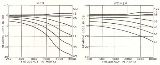
I'm surprised at the Q when the pot is near the extreme high end. Looks like if you want flat as possible, around 3.3 ohms is the spot and you're still only about -3dB at 20kHz. With the pot at 5.5, you get a substantial "old man hearing" compensator, but if this chart is to be believed, it doesn't begin to compensate:
In the AudioCircuit someone inquired about improving/upgrading the Spectra (Mk2123) interfaces. I believe the upgrade was above and beyond replacing caps or resistors. In the thread, Roy Esposito who used to work at Acoustat in Florida and still does repair work on Acoustat products responded with the following "You are sadly mistaken about the MK2123 Rockford iterations being oh-so-perfect and not in need of corrections or service. The designed-in distortion is measurable. And curable. You have also been mistaken in the past praising Acoustat/Rockford\'s Ultrasonic Bias Supply, over the original Bias system used in many of the later interfaces".
Would anybody know what the issues are with the Spectra interfaces and what improvements can be made as I am working on my interfaces at this time during the quarantine. I hope you are all well and thank you for any input.
Regards,
gwho
Roy seems to have issues with anything developed by Acoustat after he left the company, including Spectra and the Ultrasonic bias power supply. My suggestion is to spend your time listening to music rather than chasing someone's bitter attitude. I am glad Roy is there for people who need genuine repairs to their broken speakers and electronics, but I don't understand his automatic poo-pooing on anything done after the Hafler and Rockford acquisitions. If it ain't broke, don't fix it.
And BTW, Acoustat never claimed any sonic improvement with the ultrasonic bias supply. It was a change meant to circumvent European safety-agency approvals. By using a wall transformer, the burden of safety-agency approvals was placed on the manufacturer of the wall transformer, rather than on Acoustat. A speaker with the ultrasonic supply is no longer a mains-powered device, and therefore no longer requires safety-agency approvals. This is why so many devices are wall-wart powered these days!
But there are two important advantages of the ultrasonic supply: the supply is both regulated, and adjustable. The original supply had neither of these features.
It is most likely a loose stator wire with a number of broken glue points in a row. You can track it down by pulling down the sock and carefully checking the glue points on the louvers. When you find them, carefully put a dab of model glue on each one. Keep the speaker upright to prevent glue from dropping accidentally on the mylar.
Before looking for broken wires (which might be the case) I suggest a thorough vacuuming of the panels, front & back. This should be done with the speaker completely discharged and the grill cloth removed. You can also supplement this process with a gentle application of compressed air. You may need to repeat the process several times before it's cured.
Also keep in mind that the speaker will rattle or buzz when it reaches its low-frequency excursion limit, so you may be asking too much from the speaker.
Thanks for the plots bolserst. I think I expected more difference between the two circuit designs. The higher low frequency content of the MK-121 version I would guess is due to the direct non-capacitive path through the pot that doesn't exist in the C version.
I'm surprised at the Q when the pot is near the extreme high end. Looks like if you want flat as possible, around 3.3 ohms is the spot and you're still only about -3dB at 20kHz. With the pot at 5.5, you get a substantial "old man hearing" compensator, but if this chart is to be believed, it doesn't begin to compensate:
The intent of the "C Mod" was not to change the HF response, but to decrease over-saturation of the HF transformer, and hence reduce distortion. Therefore, one shouldn't expect a significant difference in HF response.
And I could be wrong about this, but I believe the frequency response plots posted previously are for the drive signal presented to the panels, and not the acoustic response of the speaker. All ESLs require considerable equalization, at both high and low frequencies, to achieve "flat" in-room frequency response.
If you were after the same HF level you had before the “C”mod, you would position the pot in the same position. But, as AAMan mentioned, you should feel free to adjust the HF pot to provide the HF level you like…that is what it is there for. The “best” position can depend on how much you have the panels toed in and how live/dead your room is.I did the "C" mod to my MK121 interfaces using a 10ohm resistor and keeping the variable pot. Where should that be setting? I have it at the noon (12 o'clock) position. The manual says use it at the 3 o'clock position, but that was with a stock MK121 .
The difference in midrange response between the two versions arises because of the interaction in the mixer portion of the circuit. The 1st order HP network(57uF/~15ohm) on the low end of the HF transformer on the MK-121C version comes with additional phase lag. So in the mixer, the output from the MK-121C HF transformer doesn’t contribute as much to the summation with the LF transformer in the midrange below 2kHz. This HP network is what keeps the MK121C HF transformer from saturating as easily and avoid distortion; as mentioned by AAMan, this was the purpose of the Cmod. By contrast the MK121 transformer is essentially running full range. The portion of the resistor in parallel with the 230uF capacitor provides damping of the resonance between the 230uF capacitance and the primary inductance of the transformer.…The higher low frequency content of the MK-121 version I would guess is due to the direct non-capacitive path through the pot that doesn't exist in the C version.
If desired, the electrical response of the MK-121C interface can be made to closely match the MK-121 interface by changing the mixer resistors from 50K to 35K.
Remember these are plots of the electrical response of the interface. Once the acoustic behavior of the ESL panel is accounted for, some amount of electrical response peaking is required to produce an overall flat electro-acoustic response.I'm surprised at the Q when the pot is near the extreme high end. Looks like if you want flat as possible, around 3.3 ohms is the spot and you're still only about -3dB at 20kHz.
See this post for more details. Help with esl simulator
In particular note:
- HF rolloff due to mass of the diaphragm shown in Attachment #4
- HF rolloff due to listening slightly away from directly on-axis shown in Attachment #3
Last edited:
It turned out to be the painting on the wall behind the speaker rattling against the wall. Silly me.
You are going to be in trouble when you get a sub!
The reason I focus on loose wires is because I have lots of panels and all of them have places where the glue has given out. However I have never experienced the symptoms mentioned or the bottoming out rattle you mention here. I listen to mostly classic rock/pop music 12ft. away with peaks of 110db at my listening position regularly. Lots of big transients there. I have never heard any of that bad stuff, mind you I do not rotate my stockpile of panels either. Could be I just happen to have a very well made set currently in my Monitor 3s.Before looking for broken wires (which might be the case) I suggest a thorough vacuuming of the panels, front & back. This should be done with the speaker completely discharged and the grill cloth removed. You can also supplement this process with a gentle application of compressed air. You may need to repeat the process several times before it's cured.
Also keep in mind that the speaker will rattle or buzz when it reaches its low-frequency excursion limit, so you may be asking too much from the speaker.
Excellent developmentIt turned out to be the painting on the wall behind the speaker rattling against the wall. Silly me.
")
Has anyone experimented with super tweeters? I added the Aperion ribbon tweeters to my system about 6 months ago and after a lot of tweaking, I can honestly say they are pretty impressive. It was a long journey, but I knew they had potential so I remained persistent. I’m not sure I could listen without them now. After fighting with comb filtering and other acoustic anomalies, I finally settled on placing them on stands between and slightly behind my Spectra 66’s. Unlike some super tweeters that only operate in inaudible frequencies, these come in around 8khz and have selectable crossover and attenuation. I have found subtle to be best, much like addition of a good subwoofer. Don’t overpower the main speakers, just augment the extremes enough to add air and presence. They were cheap enough and I would definitely recommend giving them a try.
An externally hosted image should be here but it was not working when we last tested it.
Acoustat TNT 200 Oscillation
Anyone have any experience with this amp oscillating?
I short the input and oscillation goes away.
A 10K load and oscillation returns. D6,D7 and D8 were removed as a mod, not sure if these mitigate oscillation or not. Also, C6,C7 look like different parts compared to left channel but are .1uf parts.
You should post this in the solid state amplifier section. This thread concerns Acoustat's speakers. You'll get better response in the amplifier section.
- Home
- Loudspeakers
- Planars & Exotics
- Acoustat Answer Man is here