Quick question - Spectra 1100
I have pulled out the interfaces for my Spectra 1100s. I cannot find a label stating 5K for measurement on the exposed side of the printed circuit board (is it on the other side?). Would anyone know the specifc location for the high voltage measurement node on the 1100 interface.
Best Regards,
gwho
I have pulled out the interfaces for my Spectra 1100s. I cannot find a label stating 5K for measurement on the exposed side of the printed circuit board (is it on the other side?). Would anyone know the specifc location for the high voltage measurement node on the 1100 interface.
Best Regards,
gwho
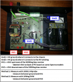
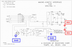
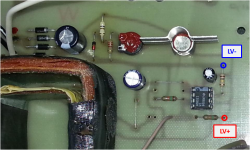
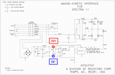
Depending whether you are measuring with a 1000:1 HV probe(method 1) or a standard DVM with 10Meg input impedance(method 2) you will need to measure at different locations. Hopefully attached pics and AAman's *.pdf writeup on the procedure will provide the info you need.
Attachments
Comparisons between the MK-121 and MK-121C electrical response posted here: All Acoustat panels can giveIt's a strange circuit which adjusts from shorting the capacitors to partially bypassing them with a resistor. I'd like to see a plot of various settings vs. frequency response.
*** Note the correction to attachments #4 & 5 in the subsequent post
You may also be interested to see electrical response with varying mixer resistance and bass tap positions.
Open CLS II stators - the best way to do it?
I would like to mention one oddity when I tried to adjust the bias measurement for the Spectra 1100 speakers. From another post, it state to adjust the potentiometer to 4.3V using the high voltage probe (1000/1). On one speaker I could rotate the pot more than 180 degrees and easily got 4.3V and above. On the other speaker, the pot would only turn about 90 degrees. I was only able to get it to reach 3.4V. I did adjust both speakers to the 3.4V but am wondering if I should replace the potentiometer or just use them at the lower voltage.
Regards,
gwho
Regards,
gwho
Hmmmm...are the pots of identical construction? If so, seems like they should operate over the same rotation angle range.
You might measure the LV that is powering the oscillator to see if it is similar when adjusted for matching 3.4V output from the multiplier. If it is, this would indicate that it is likely the pot that is limited to 90deg rotation that is at fault.
One other question, do you know what the input impedance is of your HV probe?
(or can you share make and model)
***Forgot to mention the LV should be in the neighborhood of 15VDC.
Attachments
Last edited:
Thank you for the reply. I have fluke 77 meter with the fluke 80k-6 probe. The pots do look identical. Both had some type of glue on them to prevent them from being turned. I did not want to force the one that only turns 90 degrees because it felt like I would strip the screw slot if I forced it. Is the pot a the 1K pot coupled to the base of the transistor?
Regards,
Gary
Regards,
Gary
Yessir, that is it....Is the pot a the 1K pot coupled to the base of the transistor
Thanks for details on your HV probe. Most HV probes have input impedance of 1000Meg. The 80K6 has input impedance of 75Meg. That is plenty high to keep from loading down the ultrasonic bias supply. But, be aware that you will get lower readings on the older 60Hz bias supplies in the MK-121 type interfaces with your HV probe than with one having 1000Meg input impedance.
Last edited:
Bolserst,
Do you think the probe is loading the circuit to the point where the 3.4V I read is close to 5KV or should I replace the pot that only has a 1/4 turn. Is the 1K printed circuit board pot a generic device (no voltage or current requirements) or does it have to have a specific rating?
Thank you for all the help. I appreciate it.
Regards,
gwho
No, I don't think your probe is loading down the ultrasonic bias circuit enough to significantly change the reading. A change from 4.3 to 4.2 is about all I would anticipate. Only on the older 60hz supplies would you see much change. There it would read something like 2.5 instead of 4.3.
Hopefully a bit of contact cleaner and working the trimmer a bit will get it to break free.
If you need to replace it, the voltage and current requirements are low for the trimmer. Something like this (or similar) will work fine.
PT10LV10-102A2020-PM-S Amphenol Piher | Mouser
Hopefully a bit of contact cleaner and working the trimmer a bit will get it to break free.
If you need to replace it, the voltage and current requirements are low for the trimmer. Something like this (or similar) will work fine.
PT10LV10-102A2020-PM-S Amphenol Piher | Mouser
Bolserst….Can you give us one more, time what a standard DVM with 10Meg input impedance reads in the older MK121 bias output is?..
At the Red bias wire out put on the board..I can not find your post I have seen before...is it a reading of 85-90 volts =5k?
Thanks so much for your time
At the Red bias wire out put on the board..I can not find your post I have seen before...is it a reading of 85-90 volts =5k?
Thanks so much for your time
No, I don't think your probe is loading down the ultrasonic bias circuit enough to significantly change the reading. A change from 4.3 to 4.2 is about all I would anticipate. Only on the older 60hz supplies would you see much change. There it would read something like 2.5 instead of 4.3
I don't understand why you suggest that a HV probe will load the older 60Hz supplies more than the ultrasonic supplies. The voltage quintuplers and outfeed 500M-ohm resistors are the same for both supplies. Therefore, for a given measurement method and device, I would expect identical readings on either style of bias supply. The only difference is that the ultrasonic supply is both adjustable and regulated (but note that regulation is in the low-voltage front end only, and does not compensate for HV droop).
The difference is because the ultrasonic bias supplies are replenishing the multiplier chain with HV pulses at a ~25kHz rate whereas the older supplies are working at 60Hz. This results in the effective source impedance of the multiplier being much lower for the ultrasonic bias supply. To put some rough order of magnitude numbers to it, the 60Hz supply behaves like a 5kV source with impedance of ~100Meg. The ultrasonic supply behaves like 5kV source with impedance of ~1Meg. So if you are measuring with a HV probe upstream of the 500Meg bias resistor, the 75Meg vs 1000Meg HV probe will show much less difference with the ultrasonic supply than with the 60Hz supply.
It should read in the 75-80V range...
what a standard DVM with 10Meg input impedance reads in the older MK121 bias ...At the Red bias wire out put on the board.
I follow your logic, but not sure it translates into a real world difference. At the factory, there was no change in bias measurement standards when we converted over to the ultrasonic supply. I suspect the high effective output impedance of the multiplier + constant-charge resistor more than swamps-out any difference in the charge rate. Note that my instructions on bias measurement make no distinction between 60 Hz and ultrasonic supplies, other than the adjustability of the latter.
I was a bit puzzled by your comment until I located the factory measurement method you described in another thread (How to measure bias voltage on Acoustat). It has you measuring downstream of the 500Meg bias resistor. This would make the source impedance ~600Meg for the 60Hz supply and ~500Meg for ultrasonic supply. With a 1000Meg HV probe, the measured voltage would only change about 5% and easily fall into the 3000-3500 range you mention for both the 60Hz and ultrasonic supplies.
I was describing what to expect when measuring upstream of the 500Meg resistor(Method 1 in attached *.pdf). At this measuring point the source impedance is varying by a factor of 100, from ~100Meg(60Hz) to ~1Meg(ultrasonic). This is why switching between a 1000Meg probe to a 75Meg probe would affect the reading significantly with the 60Hz supply, but hardly at all for the ultrasonic supply.
I was describing what to expect when measuring upstream of the 500Meg resistor(Method 1 in attached *.pdf). At this measuring point the source impedance is varying by a factor of 100, from ~100Meg(60Hz) to ~1Meg(ultrasonic). This is why switching between a 1000Meg probe to a 75Meg probe would affect the reading significantly with the 60Hz supply, but hardly at all for the ultrasonic supply.
Attachments
Comparisons between the MK-121 and MK-121C electrical response posted here: All Acoustat panels can give
*** Note the correction to attachments #4 & 5 in the subsequent post
You may also be interested to see electrical response with varying mixer resistance and bass tap positions.
Open CLS II stators - the best way to do it?
Thanks bolserst. If I'm understanding it correctly, the plots compare the frequency responses for the different interface configurations C-mod vs. earlier but at a fixed hi frequency pot setting. I was hoping to see the frequency response curves at different settings of the hi freq pot.
Correct. Hi frequency settings were similar for C-mod vs. Pre-Cmod.
I thought the comparison would address the ~2dB difference in the mid-range mixer region that you were asking Tyu about in Post #2360.
But, looking at your post again I see you were actually interested in the resistor settings.
I'll see if I can locate the LTspice files this weekend and run some HF pot setting trends for both versions to post.
I have a pair of model 3s. Once in a while I cn hear a buzzing in one speaker. It's very slight but definitely there. Are there any suggestions on how to diagnose?
Could be just dust or dirt in the panel. Use an air compressor to blow it out or you could try to vacuum the panel. I did both, several times, when I rebuilt my 2+2's.
- Home
- Loudspeakers
- Planars & Exotics
- Acoustat Answer Man is here