tyu you're talking about the air mod right? if it's that good, that you don't need the ribbons I'll have to look into that. my second thought would be improving the imaging, would getting new frames and moving to a 1+1 or a 2 setup improve that (by taking the panels out of mine and putting them into a frame like a 1+1 or a 2)? As they are they seem pretty beamy
I owned 2+2s from their very inception in 1982 for over twenty years. Updated to OFC wired panels. Blue Medallions. Red Medallions. Replaced the horribly oxidized Monster cable. Bypassed the fuses. Replaced the burlap socks with spandex. They remained a good sounding, but still head-in-a-vise speaker. Even after using laser pointers and string-to-head for precise placement.tyu you're talking about the air mod right? if it's that good, that you don't need the ribbons I'll have to look into that. my second thought would be improving the imaging, would getting new frames and moving to a 1+1 or a 2 setup improve that (by taking the panels out of mine and putting them into a frame like a 1+1 or a 2)? As they are they seem pretty beamy
The 1+1s are eminently better in that regard to these ears. Especially with Roy Esposito's enhancements.
Attachments
Last edited:
I think you must have misunderstood the description of the Air mod.Wow....for some time i have been talking about droping the 500mg at the end of the Bias panel feed to 5-10 mg.....i have 3mg in now an the topend is the best i have ever had out of Any Acoustat mod yet......
looks like the so called Air mod has (No)meg ohms Res...At all....??
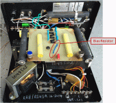
The Bias Resistor was not removed.
It was replaced with what looks like an Ohmite Thick Film Planar HV resistor.
I can't tell you what the resistance is, but it isn't zero.
Attachments
Last edited:
Well Thinker 1920...
i got in the Acoustats in the 80s.....i was in the Audio Biz then...Jim was making Acoustat here in Fl...... spoke to him minny times.....He told me he had just the panels hanging in his shop.....just the panels....
An thay sounded great
I got The Xs with the servo tube amps............Well did not take long for me to see the 1+1 panel setup sound better than any other Acoustat....well to me....
looks like most say the same thing.....but did not have the mids of the 2+2s M3 M4s......
But took a long time to get it all worket out........An what it was .....No ESL i have ever owend that the panels only 2-3" off the floor well not work for my ear.....an the 1+1 an the 2+2s top of the botten panels are right at ear level......this part of the panels has the lest output..an lest movement......the panels middel sounds best an the most movement....
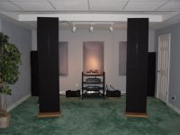
An the panels have setup to be Flat.....That what the 1+1s got going for it....Flat.....Like the Pic...Killer sound.....
Well why not....My Quad 57s were flat.....my Apogee are ....My Magnepanes
Most of what i like in a panel speaker.....are Flat...Hehe
Long live Acoustats......
i got in the Acoustats in the 80s.....i was in the Audio Biz then...Jim was making Acoustat here in Fl...... spoke to him minny times.....He told me he had just the panels hanging in his shop.....just the panels....
An thay sounded great
I got The Xs with the servo tube amps............Well did not take long for me to see the 1+1 panel setup sound better than any other Acoustat....well to me....
looks like most say the same thing.....but did not have the mids of the 2+2s M3 M4s......
But took a long time to get it all worket out........An what it was .....No ESL i have ever owend that the panels only 2-3" off the floor well not work for my ear.....an the 1+1 an the 2+2s top of the botten panels are right at ear level......this part of the panels has the lest output..an lest movement......the panels middel sounds best an the most movement....
An the panels have setup to be Flat.....That what the 1+1s got going for it....Flat.....Like the Pic...Killer sound.....
Well why not....My Quad 57s were flat.....my Apogee are ....My Magnepanes
Most of what i like in a panel speaker.....are Flat...Hehe
Long live Acoustats......
Attachments
Last edited:
The Bias Resistor was not removed.
It was replaced with what looks like an Ohmite Thick Film Planar HV resistor.
I can't tell you what the resistance is, but it isn't zero.
....
Thanks for the info....Look like a blue wire to me in the pic....
That ok to....i have found the better res. will give better sound on it own. But bet it not 500mg???....My be some one well tell us.......Hehe
Air Mod is the bypassing of the C Mods top 3ohms.....with what looks like a small gold dail res....
Attachments
![Acoustat_MK-121C_Interface[1].gif](/community/data/attachments/397/397279-78c32135ccd2e14f0a9acb11a320d6a7.jpg)
Last edited:
When tyu says Mg, he means Mega Ohms resistance. He is referring to the acoustat 500 Mega Ohm bias resistor, and/or the 50K Ohm bass transformer series resistor to the stators. Soundlabs does not have that series resistor to the stators, ...I shorted mine (both of them)...don't know if it really makes it better sounding yet - (need a little more critical listening), but they are there to provide an electronic "delay" of sort - like the quad ESL 63 delay... I cannot tell if the 2+2 I have are now more "beamy" with these bass tranny series resistors shorted, but I have noticed that they now sound best when I listen seated further away from the speakers than before (with the resistors). This may be a problem for me as my listening room is not long enough to make this permanent...I may remove the jumpers soon...
Last edited:
John.....i put my 50k back in when i dropet the 500mg bias res to 10-3meg........this give a 3db or more output....
this way it sound like the 500mg is in..... an the 50k are out.. but better....hehe.....just saying all i hear.....you have to go are you wont know....right.....
I Void Warrantys too.............
this way it sound like the 500mg is in..... an the 50k are out.. but better....hehe.....just saying all i hear.....you have to go are you wont know....right.....
I Void Warrantys too.............
More info on Acoustat's you can never get enough.")
Audio Haven | Acoustat
http://www.audiocircuit.com/Home-Audio/Acoustat
Audio Haven | Acoustat
http://www.audiocircuit.com/Home-Audio/Acoustat
Last edited:
Having the 500meg bias resistor does a few things - limits bias current so you don't get shocked real bad (should you unwillingly become part of the bias circuit), and also controls the recharge rate of the panel (seems to me the faster the better). Also helps prevent the diaphragm from going up in flames....
I would rather raise the bias voltage than reduce the bias resistor by adding another ladder rung.
I would rather raise the bias voltage than reduce the bias resistor by adding another ladder rung.
My Acoustat 121 Setup is not stock like yours...Also i live were the Humity is over 60% 320 day a year.....An my 121 bias is outboard so i can set my bias from 4-7k........Thinker..... i would not go lower 20-10mg
Youll see the diff......20mg is vary low ...from 500mg.....as i posted MartinLogan is at 60mg with the stock bias feeds...I drop my ML to 10mg..thay use 1cent 1/4 carbons like you can get at ratshak.......an these are ESL over $10k.......hehe
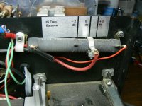
In the pic you can see the res...at the end of the red caps......
Youll see the diff......20mg is vary low ...from 500mg.....as i posted MartinLogan is at 60mg with the stock bias feeds...I drop my ML to 10mg..thay use 1cent 1/4 carbons like you can get at ratshak.......an these are ESL over $10k.......hehe
In the pic you can see the res...at the end of the red caps......
Attachments
![aerius%20boards[1].jpg](/community/data/attachments/397/397699-e1602f8121daf872532775f3075da8d7.jpg)
Good point John.....
I did the same thing for years...An still fell the Stock biass if over 20 years old sould have new an better partes...It on all the time 24/7..but puting a biger pump on a 1/6" pipe....Dose not work.....drop the 500meg down to 10-20meg....well be like A 1/2" pipe an the panels can chargup faster.......John...(seems to me the faster the better). Also helps prevent the diaphragm from going up in flames.... Look i dont no about the flames.....SL uses NO bias feed res...an there bias is ran at 7-8k......I run at 3mg an see no diff..just better sound....An this is the Ezeys Mod ever!
Heres what i get sound wise...Less Sag.. with sag the bass gos up the highs roll off.... panels charg up faster an can keepup with the sound ...i get more output....an way better highs an great bass..... i never got better highs with higher bias..just a more output...an if you dont like this go back to the stock!....
Like i say ....if you dont go you dont Know....
These old Acoustat panels are great....But i always had to use ribbons to get the topend .....Droping the bias feeder....i dont need to now..
An My Acoustats topend is better than my buds SL M-1 with new tro trans....an that what he states.....gofig....
Last edited:
The Bias Resistor was not removed.
It was replaced with what looks like an Ohmite Thick Film Planar HV resistor.
I can't tell you what the resistance is, but it isn't zero.
....
Thanks for the info....Look like a blue wire to me in the pic....
That ok to....i have found the better res. will give better sound on it own. But bet it not 500mg???....My be some one well tell us.......Hehe
Air Mod is the bypassing of the C Mods top 3ohms.....with what looks like a small gold dail res....
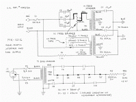
The hi freq level potentiometer seems to be wrongly wired, it must be better to
connect the hi transformer input to the pot's slider?
The hi freq level potentiometer seems to be wrongly wired, it must be better to
connect the hi transformer input to the pot's slider?
Relly.....i see the 3ohm to in the pic.. an if this is dropet to 1ohm you get more highs.....This is hard to get speaker set the same...So Roys Mod Lets this be done ezer......the slider is set at 13ohms...from pos-to neg....so the amp see the 13ohms all the time...that not removed in the Air mod...are it well be what amp well we cook to day mod.....hehe....what do you see??
Attachments
![Acoustat_MK-121C_Interface[1].gif](/community/data/attachments/397/397780-78c32135ccd2e14f0a9acb11a320d6a7.jpg)
Last edited:
Having the 500meg bias resistor does a few things - limits bias current so you don't get shocked real bad (should you unwillingly become part of the bias circuit), and also controls the recharge rate of the panel (seems to me the faster the better). Also helps prevent the diaphragm from going up in flames....
I would rather raise the bias voltage than reduce the bias resistor by adding another ladder rung.
Agree 100%
Main function is limiting the damage to film in case of arc. Small hole, no problem, big hole, big problem. 100MO (MegaOhm), 300MO, 500MO - I don't think it makes any sonic difference but the higher the value, the better protection of the film.
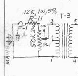
Even easier and certainly more flexible solution than adding step(s) to the multiplier ladder is over-sizing (20% higher will be more than sufficient for any needs) AC supply and putting a voltage divider ("bias control") at the AC (110/220) input like Soundlab did on their early panels. I have an A2x where the voltage divider is 12k/1W shunted across the AC with a 50k/2W pot. Works great, and it's very easy to adjust.
With your ear close to the stator wind the pot up, say, 5-10 degrees at the time. Faint pops go up as the charge builds up, then they disappear. Keep raising the voltage in these 5-10deg steps until you notice that pops are not disappearing any longer, then back up just a tiny bit until they are gone. Biasing done.
As far as the "Air mod"... if it really is only jumping the variable wire-wound resistor (VR), how is that any different from turning the VR all the way to 0 resistance?
However, the sonic effects of 0-resistance VR will depend on which version of MK121 interface it's applied on.
Early MK121 had the VR in series with the signal, acting as a rather crude voltage divider between a straight line to HF audio transformer on one leg, and a total of 230uF capacitance on the other.
0 resistance VR in this case meant no filtering (almost - internal resistance of capacitors) of the HF signal and probably caused quite a few blown HF transformers because they would be receiving the full frequency (and energy) as the LF transformer.
MK121 C-Mod (can't remember what the "B" was about) puts the VR in the "shunt" across the HF transformer primary, acting as much finer voltage divider (6ohm variable + 10ohm fixed), and with negligible effect on the capacitance filter that precedes it.
In this case, setting the VR to 0 resistance lowers the resistance of the "shunt" and conducts MORE through the shunt compared to the HV Trf primary leg.
Thus, maximum shunt leg resistance = maximum HF output.
Without knowing the HV Trf primary AC/DC resistance, I cannot for certain calculate the effect of the voltage divider, nor can I calculate the effect of the much reduced HF filter capacitance of the C-mod, but it is absolutely certain that the C-Mod acts as a 1st order HF (HiPass) filter at a much higher frequency than original MK121, which protects the HF Trf a whole lot more.
Some assumptions for equation purposes:
Since the total shunt resistance is 16ohm, I will assume that the HF Trf primary is also 16ohm, producing the total DC resistance of 8ohm. Assuming that impedance is similar to resistance, capacitance value of 57uF in the 1st order filter means a HiPass from 350Hz (which sounds about right).
Finally, the 1ohm resistor on the LF Trf primary.
It's sole purpose is to prevent transformer impedance from dropping to very uncomfortable 0. I remember reading somewhere that it was actually measured dropping down to 1ohm so Acoustat thought it's safer to put another 1ohm in series to protect the amplifiers from going into short-circuit panic. Does this affect the LF sonics? Honestly, no idea. Soundlab has 30ohm (!!!) 100w (!!!) in series and I honestly cannot say that it differs much from Acoustat in terms of perceived speed or definition.
Mike
Working: Acoustat M3 - SoundLab A2X - Acoustat Spectra 44 - Martin Logan CLS (1)
Awaiting bench time: Arcing Quad ESL63.
Future Projects: brand new Martin Logan CLS-II panels and 2nd hand Odyssey panels for full custom from-scratch builds
Not at all - it's just a shunt across the HF Trf primary. Full swing it both ways, medium effect. Even if you completely remove the shunt leg, you end up with HF Trf primary resistance/impedance as the load. It will just be LOUD.But if the pot is turned to the lowest level, the amp will be short circuited at high freqs...
I enclose my suggestion..
Edit: Just in case of misunderstanding:
Shunt resitance can never be 0 because it either contains a fixed 10ohm resistor (if the original 6ohm VR was used), or a fixed 13ohm resistor (if a 3ohm VR was used).
Last edited:
But if the pot is turned to the lowest level, the amp will be short circuited at high freqs...
On all the OEM Acoustats I have worked with, it is physically impossible to adjust the tap on the slider resistor below the half way point.(see attached pic)
Acoustat Answer Man may know if there were ever MK-121 interfaces made where the tap was adjustable over the whole range.
I would bet no.
Look at the schematic Tyu attached in post#996:Not at all - it's just a shunt across the HF Trf primary.
http://www.diyaudio.com/forums/planars-exotics/183168-acoustat-answer-man-here-100.html#post3985864
"IF" the slider could be adjusted all the way down, the amplifier would see a short thru the capacitors to ground at high frequencies.
I don't think it is possible to adjust the slider in this manner on OEM interfaces.
Attachments
- Home
- Loudspeakers
- Planars & Exotics
- Acoustat Answer Man is here