What's your real life experience with NO DUST COVERS?
I've heard one pair of ESL63s with no dustcovers and they did have less of the mid/HF delayed resonance that is their main audible fault.
But Peter Walker said they would need cleaning or even new diaphragms after a month .. sometimes after a week.
Obviously environment would dictate how long the panel would last without a dust cover. I get a lot of quads in with pretty grimy dust covers and the panels inside are pristine; except for the fact that the glue or diaphragms have failed. The dust has to get to the dust cover through the grille cloth and grilles and it still does.
Certain ranges of the quad 63's had extra bridge pieces with dacron that pushed on the middle-ish of the dust covers. I should do some measurements of a 63 with the plain dust cover and also with those funky things on them.
Also the newer ESL's and the early 63's have tensioned dust covers , while the majority of the 63 production run had loose dust covers in my experience. You can tell by picking one up and moving it around and you'll hear a woosh woosh noise of the loose dust cover moving around.
Sheldon
Data point: recently put back into service some panels I made in early 70's. When in use and when in storage, I just throw a sheet of lovely synthetic paisley fabric over the panels. Working now as well as ever....I'm really after real life experience with ESLs without dustcover....
The Dayton-Wright cells have rather wide spacing and a bit of a dust bin at the bottom of each cell. I vacuum and heat treat once or twice a year.
Seems as good as ever, but I didn't do REW measurements long ago to compare to.
Of course, stock DW speakers are carefully sealed and have that welding gas inside for a number of great reasons.
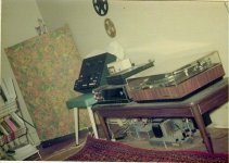
Here's a photo from 1975 using celluloid technology in common use at the time. If you're a HiFi fanatic more than 60 yrs old, you may be able to identify the gear (the fabulous KT88 amp is home-brew).
B.
Attachments
Last edited:
Hi Gents,
Curious has anyone or is it possible to build a esl exponential horn loaded panel just for mids to highs.
Josef Merhaut had an Audio Engineering Society paper: "Horn-Loaded Electrostatic Loudspeaker"
He was also granted US patent 3590169A around then.
Data point: recently put back into service some panels I made in early 70's. When in use and when in storage, I just throw a sheet of lovely synthetic paisley fabric over the panels. Working now as well as ever.
The Dayton-Wright cells have rather wide spacing and a bit of a dust bin at the bottom of each cell. I vacuum and heat treat once or twice a year.
Seems as good as ever, but I didn't do REW measurements long ago to compare to.
Of course, stock DW speakers are carefully sealed and have that welding gas inside for a number of great reasons.
Here's a photo from 1975 using celluloid technology in common use at the time. If you're a HiFi fanatic more than 60 yrs old, you may be able to identify the gear (the fabulous KT88 amp is home-brew).
B.
That receiver looks very familiar - Heathkit?
Hi Bolserst,No reason to ridicule cone-drivers. Although the basic transduction mechanism hasn’t changed in 100 years, the EML (Electro-Magnetic Loudspeaker) has evolved from crude “shaking cardboard” to linearly driven nearly perfect-pistons thanks to improvements in materials and motor configuration. Similar improvements in materials and drive configuration evolved the ESL from “flapping pig intestine” to linearly driven, nearly light as air membranes.
Only at the lowest frequencies (more than octave below resonance) does the linearity of the suspension dominate control of the cone motion. For the octave around resonance, damping is dominate. Damping in the EML is provided by the motor. Above resonance the motion of the cone is dominated by the mass of the (cone+voice coil). Since mass is constant, only the motor linearity comes into play. When trying to get an image in your mind of how EMLs and ESLs differ, focus on what controls the motion of the piston(cone for EML, diaphragm for ESL) over the majority of the working bandwidth. With EMLs it is piston mass which is constant. With ESLs it is the airload on the piston which actually varies considerably with frequency.
Consider the attached mechanical/acoustic analogical model for a dipole transducer. This is an impedance analogy where voltage represents mechanical force or acoustic pressure, and current represents mechanical velocity or acoustic volume velocity. Again, if we stay focused on the majority of the working bandwidth, the only real difference between the EML and the ESL is the piston mass of the EML represented by inductor Mmd. Note that fc is constant(ie frequency independent) for both transducer types if driven by the typical voltage source amplifer.
Attachment #2 shows the resulting far field on-axis response for EML and ESL operated as dipole pistons, or when placed in an infinite baffle. Let me know if anybody is interested in more details on why they behave this way or how you get these response from the model discussed above.
- For the ESL, constant motor force (fc) results in constant radiation force (fr), and thus a constant pressure (Po) applied to the airload (ZR+iZX).
- For the EML, since F=ma, constant motor force (fc) results in constant piston acceleration or velocity (uc) that falls -6dB with increasing frequency.
***NOTE: ka=1 represents frequency for which piston diameter is roughly 1/3 wavelength.
1.) Can you explain the reason of the attachment #2 response for ESL and EML, why is it a rising response as ka increases (as frequency increases above fs) for the ESL and it's flat line response for the EML? Is this because as ka>1, the dispersion starts to narrow (beams)?
2.) from the attachment 1 (radiation impedance curve), the air mass load (XR) decreases as ka increases. The air mass only become significant close to ka=1, is this correct?
Wow! - its a while since this thread was active ")
Radiation impedance comprises two parts.
The resistive part corresponds to air being compressed to form a wave, and the wave carrying energy away from the speaker. The acoustic energy loss is the equivalent of the energy dissipated in a resistor.
The other part of the impedance looks like an inductance and corresponds to air movement without compression - its like the sloshing of coffee around the spoon when you stir coffee, or when you shake an unfolded bed sheet - the air trapped next to the sheet gives the sheet extra mass. The impedance is like that of a constant inductance, Z = wL, it increases with frequency. The same happens with the airmass - it causes an increasing impedance proportional to the mass of the trapped air.
At high frequencies, above ka = 1, once the wavelength falls below the membrane/piston dimensions, its almost like the air cant find its way around the speaker anymore, and almost all of the membrane movement results in air compression so the inductive part falls away and impedance becomes increasingly like a pure resistance and constant with frequency.
Rod
Above ka=1, narrowing dispersion increases the directivity index for any flat piston radiator(EMLs or ESLs) resulting in on-axis response that increases 6dB/oct relative to the power response(ie total sum of radiated acoustic power in all directions)1.) Can you explain the reason of the attachment #2 response for ESL and EML, why is it a rising response as ka increases (as frequency increases above fs) for the ESL and it's flat line response for the EML? Is this because as ka>1, the dispersion starts to narrow (beams)?
- For EMLs the power response falls -6dB/oct above ka=1 because of its mass controlled nature. Add in the directivity index and on-axis response remains flat.
- For ESLs the power response is flat above ka=1 because its motion is controlled by the radiation impedance. Add in the directivity index and on-axis response rises at +6dB/oct.
Radiation impedance curves are dependent on if the piston is rigid or resilient and if there is any baffling around the piston. But, as golfnut already described, the mass or reactive portion of the airload is constant for ka<<1. The reason the Xs curve slopes upward is because the plot is for the mechanical impedance of that mass which is calculated by multiplying the mass by (2*pi*frequency).2.) from the attachment 1 (radiation impedance curve), the air mass load (XR) decreases as ka increases. The air mass only become significant close to ka=1, is this correct?

You can get a rough idea of the magnitude of the airload mass on a dipole piston using the LF(Low Frequency) approximations:
LF Airload Mass(rigid piston) = 2.67 * a^3 * rho (kg)
LF Airload Mass(resilient piston) = 4.93 * a^3 * rho (kg)
where:
a = radius of diaphragm or piston (m)
rho = density of air = 1.20 (kg/m^3)
With proportionality to radius cubed, the airload mass rises quickly with increasing radius.
For example, an ESL with diaphragm having 0.5m radius:
LF Airload Mass = 4.93 * (0.5^3) * 1.2 = 0.74 kg !!!
Golfnut, Bolserst, thank you.
- it's interesting that the air mass load decreases to zero above ka=1, and it turn into purely acoustic resistance. I'm trying to understand intuitively, Golfnut gave an explanation that the air can't go around the membrane, but it should still 'feels' the air mass in front and the back of it. May be due to the fact that the excursion is very small as frequency increases?
- The EML have a magnetic damping/braking (motional EMF), as any conductor moving in a magnetic field will induced currents that opposes the motion of the conductor. Is there such damping or braking mechanism with ESL? after all it's a microphone too
- Is there a point where the ESL will have the mass-controlled region high up in the frequency range? The EML will start to have mass-controlled region lower in frequency.
- The ESL should also have the compliance controlled region too, similar to the EML, at ka<<1, correct?
1) Radiation impedance is a tough concept for most people to understand. Attached is a paper I found helpful.
Also, here is an alternate description of why radiation impedance changes with frequency which some find intuitive.
When a piston vibrates in air, two things happen simultaneously:
2) There is, but it is extremely weak. The transduction coefficient for ESLs is on the order of 1000 – 10000 times smaller than for EMLs so trying to damp the mechanical domain from the electrical domain is rather ineffective.
3) Yes. Once the reactive load of the diaphragm mass becomes similar in magnitude to the radiation resistance the power response will become mass controlled, falling at -6dB/oct with increasing frequency. With typical diaphragm thicknesses, this happens near or above the top octave. Here is a post showing measurements of this for a few common diaphragm thicknesses.
https://www.diyaudio.com/community/threads/electrostatic-speakers-as-microphones.231062/post-3427260
4) Yes. ESLs have a compliance controlled region below their fundamental resonance just like EMLs.
Also, here is an alternate description of why radiation impedance changes with frequency which some find intuitive.
When a piston vibrates in air, two things happen simultaneously:
- it compresses/expands the air (produces sound waves)
- it moves the air back and forth without compression (does not produce sound waves)
2) There is, but it is extremely weak. The transduction coefficient for ESLs is on the order of 1000 – 10000 times smaller than for EMLs so trying to damp the mechanical domain from the electrical domain is rather ineffective.
3) Yes. Once the reactive load of the diaphragm mass becomes similar in magnitude to the radiation resistance the power response will become mass controlled, falling at -6dB/oct with increasing frequency. With typical diaphragm thicknesses, this happens near or above the top octave. Here is a post showing measurements of this for a few common diaphragm thicknesses.
https://www.diyaudio.com/community/threads/electrostatic-speakers-as-microphones.231062/post-3427260
4) Yes. ESLs have a compliance controlled region below their fundamental resonance just like EMLs.
Attachments
The EML have a magnetic damping/braking (motional EMF), as any conductor moving in a magnetic field will induced currents that opposes the motion of the conductor. Is there such damping or braking mechanism with ESL? after all it's a microphone too
I don't think it's accurate to say the transduction coeff. for ESLs is 'ineffective'. Most ESLs are 'resistive' controlled by the air load over most of their frequency range so it's more accurate to say that this resistive damping is much greater than any 'electrical' damping.2) There is, but it is extremely weak. The transduction coefficient for ESLs is on the order of 1000 – 10000 times smaller than for EMLs so trying to damp the mechanical domain from the electrical domain is rather ineffective.
You would get a similar effect if your EML had a very large, light diaphragm.
The inherent ESL transduction coeff is actually very high. But most (all?) implementations waste this.
If you make an ESL 63 sized speaker which closely approached this inherent sensitivity, it would be 94dB/W @ 1m
BTW, that's why I was investigating supa dupa inductors for a Walker/Baxandall ESL
Yes, ESL is efficient, mostly due to the use of transformer, and that the acoustic resistance can be much more than the electrical damping, but what causes this electrical damping? is it due the membrane moving from its equilibrium middle position and that changes the total capacitance...? with EML, the motional EMF is due to having a conductor moving in a magnetic field.I don't think it's accurate to say the transduction coeff. for ESLs is 'ineffective'. Most ESLs are 'resistive' controlled by the air load over most of their frequency range so it's more accurate to say that this resistive damping is much greater than any 'electrical' damping.
No. ESL efficiency is nothing to do with the transformer but simply the voltage and current levels involved.Yes, ESL is efficient, mostly due to the use of transformer, and that the acoustic resistance can be much more than the electrical damping.
In a Push-Pull Constant Charge ESL, the Acoustic Resistance is always much larger than the Electrical damping.
In an EML, the voice coil exerts a Force BLi on the cone ... B:Flux L:length of wire in that flux i:current through the wirebut what causes this electrical damping? is it due the membrane moving from its equilibrium middle position and that changes the total capacitance...? with EML, the motional EMF is due to having a conductor moving in a magnetic field.
When the coil moves, it generates a Voltage BLv v:velocity
BL is the Transduction coeff that connects the Electrical world with the Mechanical world
The Electrical Damping is exactly (BL)^2 / R R: DC resistance of the voice coil
I'm only a pretend ESL guru and haven't done this ESL stuff for more than 4 decades so I hope da true ESL gurus will correct the output of dis beach bum's single remaining brain cell
...The Voltage gradient between the stator plates generates a Force on the diaphragm (and air) proportional to the Charge on the diaphragm.
When the air and diaphragm move, this 'Constant' Charge moves between the stators being effectively a Current.
... I'm afraid I can't remember how to get numbers for the equivalent damping and Transduction coeff. It's the dual of the EML case which I sorta still remember
that should beNo. ESL efficiency is nothing to do with the transformer but simply the voltage and current levels involved.
The transformer is simply cos the voltage & current levels involved. The transformer has nothing to do with efficiency
Damping from the resistive airload does dominate at mid and high frequencies, but falls off very rapidly at low frequencies where it would be of the most use to damp the fundamental diaphragm resonance. (see radiation impedance plots in Post #228) ESLs can't damp diaphragm resonance below Q of 5 or so using electrical domain damping. EMLs can effect enough damping from electrical domain for Q<<1....Most ESLs are 'resistive' controlled by the air load over most of their frequency range so it's more accurate to say that this resistive damping is much greater than any 'electrical' damping.
You would get a similar effect if your EML had a very large, light diaphragm.
ESLs don't produce motional EMF like EMLs. Rather, they produce a motional current proportional to the diaphragm velocity. The simple way to think about it for constant charge ESLs, is that the total charge stored in the two diaphragm-to-stator capacitors is constant. The ratio of the charge stored in these capacitors is inversely proportional to distance between the diaphragm and corresponding stator. So as the diaphragm is moved back and forth, charge is shuttled from one stator to the other thru the transformer secondary or other conductive path. The rate of change of charge is current. The rate of change of position is velocity. So the motional current is proportional to the diaphragm velocity.... what is the details cause of this ESL motional emf?
Comparing transduction coefficients, BL = 10 is pretty typical for an EML, and ∝ = 0.002 for an ESL.
The other difference is that the EML motor behaves like a gyrator and an ESL motor like a transformer.


One consequence of this difference is that adding resistance in the electrical domain has opposite effects in the mechanical domain. For EMLs, minimizing electrical resistance provides the most damping of the mechanical system. For ESLs, resistance must be added to the electric circuit to damp the mechanical system. As mentioned previously, it isn’t very effective. As an example, here is a trend for an 400pF ESL panel with increasing resistance added in the electric circuit.

Even with 1Meg of resistance very little increase in damping is seen, and the power response is rolling off at high frequencies due to the first order LP filter formed between the series resistance and the panel capacitance. Note that as you continue to increase resistance the Q actually starts to go back up and the resonance increases to the unpolarized resonance frequency. This is because the resistance is >> impedance of the panel capacitance so you are in effect driving the panel with a current source. The negative compliance -Ce is then cancelled out by the panel capacitance Ce as explained in the Baxandall ESL chapter. It is all rather academic since so much sensitivity is lost with high series resistance that it isn’t practical anyways. If interested, experimental results for this behavior were posted here:
https://www.diyaudio.com/community/threads/current-vs-voltage-drive-esl.175918/post-2366501
The other difference is that the EML motor behaves like a gyrator and an ESL motor like a transformer.
One consequence of this difference is that adding resistance in the electrical domain has opposite effects in the mechanical domain. For EMLs, minimizing electrical resistance provides the most damping of the mechanical system. For ESLs, resistance must be added to the electric circuit to damp the mechanical system. As mentioned previously, it isn’t very effective. As an example, here is a trend for an 400pF ESL panel with increasing resistance added in the electric circuit.
Even with 1Meg of resistance very little increase in damping is seen, and the power response is rolling off at high frequencies due to the first order LP filter formed between the series resistance and the panel capacitance. Note that as you continue to increase resistance the Q actually starts to go back up and the resonance increases to the unpolarized resonance frequency. This is because the resistance is >> impedance of the panel capacitance so you are in effect driving the panel with a current source. The negative compliance -Ce is then cancelled out by the panel capacitance Ce as explained in the Baxandall ESL chapter. It is all rather academic since so much sensitivity is lost with high series resistance that it isn’t practical anyways. If interested, experimental results for this behavior were posted here:
https://www.diyaudio.com/community/threads/current-vs-voltage-drive-esl.175918/post-2366501
Thanks for all this bolsert. I was afraid I was pontificating from the wrong orifice but it looks like I wasn't .. attempts to cover up his pseudo guru ravings
But thank you for explaining clearly why attempting more 'electrical' damping on an ESL is useless
IIRC (and it was 4 decades ago) the Walker AES paper describing ESL 63 uses a somewhat different theoretical model to the 'Beranek' type models you (and I) use.
.. attempts to cover up his pseudo guru ravingsActually a 'diaphragm in free air' the size of ESL 63 needs fairly substantial bass boost and this is done by seriously under damping the 'fundamental resonance' ... so there's some heavy serendipity going onDamping from the resistive airload does dominate at mid and high frequencies, but falls off very rapidly at low frequencies where it would be of the most use to damp the fundamental diaphragm resonance.
But thank you for explaining clearly why attempting more 'electrical' damping on an ESL is useless
IIRC (and it was 4 decades ago) the Walker AES paper describing ESL 63 uses a somewhat different theoretical model to the 'Beranek' type models you (and I) use.
Thank you Bolserst, this is a very helpful analysis. Very much appreciate it.Comparing transduction coefficients, BL = 10 is pretty typical for an EML, and ∝ = 0.002 for an ESL.
The other difference is that the EML motor behaves like a gyrator and an ESL motor like a transformer.
View attachment 1030465 View attachment 1030466
One consequence of this difference is that adding resistance in the electrical domain has opposite effects in the mechanical domain. For EMLs, minimizing electrical resistance provides the most damping of the mechanical system. For ESLs, resistance must be added to the electric circuit to damp the mechanical system. As mentioned previously, it isn’t very effective. As an example, here is a trend for an 400pF ESL panel with increasing resistance added in the electric circuit.
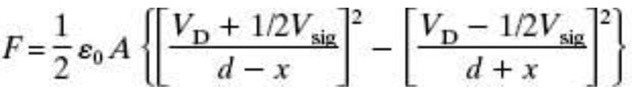
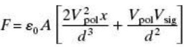
In the chapter of Borwick's book for Electrostatic (by Baxandall). In sections 3.2.2 and 3.2.3. He derived the force on the membrane (for Constant Charge), Eq. 3.12., does this Force formula already include/accounted for the mechanical damping in your post #237 above? Please see both of my attachments.
Or that the electrical damping is already accounted for in the Vsig or Vd?
Wow... that's a lot of audio power being reduced by having electrical resistance at the ESL panel, and the damping is not improved by that much.View attachment 1030467
Even with 1Meg of resistance very little increase in damping is seen, and the power response is rolling off at high frequencies due to the first order LP filter formed between the series resistance and the panel capacitance. Note that as you continue to increase resistance the Q actually starts to go back up and the resonance increases to the unpolarized resonance frequency. This is because the resistance is >> impedance of the panel capacitance so you are in effect driving the panel with a current source. The negative compliance -Ce is then cancelled out by the panel capacitance Ce as explained in the Baxandall ESL chapter. It is all rather academic since so much sensitivity is lost with high series resistance that it isn’t practical anyways. If interested, experimental results for this behavior were posted here:
https://www.diyaudio.com/community/threads/current-vs-voltage-drive-esl.175918/post-2366501
Attachments
What if we use a Direct Drive amplifier (without any transformer), then there won't be any conductive path to shuttle the charges from a stator to another. How will it electrically damp the diaphragm velocity? So there's no electrical damping when we use Direct Drive amp for ESL?ESLs don't produce motional EMF like EMLs. Rather, they produce a motional current proportional to the diaphragm velocity. The simple way to think about it for constant charge ESLs, is that the total charge stored in the two diaphragm-to-stator capacitors is constant. The ratio of the charge stored in these capacitors is inversely proportional to distance between the diaphragm and corresponding stator. So as the diaphragm is moved back and forth, charge is shuttled from one stator to the other thru the transformer secondary or other conductive path. The rate of change of charge is current. The rate of change of position is velocity. So the motional current is proportional to the diaphragm velocity.
- Home
- Loudspeakers
- Planars & Exotics
- Electrostats vs conventional drivers