Can i ask your view on the best bandwidth for ESL? Is there any merit only using ESL for midrange? Most ESL seem to misbehave over 10kHz with complex resonances and plummeting impedance.
What to you mean by best? for what purpose?, by what measure?
For all ESLs there is a trade off between midrange SPL and low cutoff frequency. So a full range ESL will give a fantastic overall sound: great stereo imaging, seamless, low distortion bass, etc, but is probably limited to 105 dB -110 dB peak. Requires very careful design and engineering - every little compromise costs mid-band SPL. The bottom end bass tends to be determined by distance between ESL and the wall behind - the refection from the rear of the ESL is out of phase with the sound from the front. So you need a lot of room.
A hybrid means an ESL can be loud, but matching the woofer to a dipole line source is is tricky.
The high frequency resonances etc can quite well modeled and managed. m
Is the rest of the system dipole?Is there any merit only using ESL for midrange?
If not, you will have problems matching directivity across the units giving a very poor Room Interface Profile .. one of the biggest determinants of speaker sound quality.
If you are going to box in your ESL, you seriously compromise its midrange performance. ALL speakers suffer from sound from the back of the transducer reflected from the back of the box. ESLs suffer even more cos their diaphragms are nearly 'transparent'.
Is the rest of the system dipole?
If not, you will have problems matching directivity across the units giving a very poor Room Interface Profile .. one of the biggest determinants of speaker sound quality.
Sure, for hours on end you can name ways drivers - of all sorts - can match or mismatch as woofers, mids, or tweeters. Yes, there are good and bad drivers. But I can't say as I've ever heard an empirically verified thought on the subject of matching.
B.
The 'empirical verification' is inSure, for hours on end you can name ways drivers - of all sorts - can match or mismatch as woofers, mids, or tweeters. Yes, there are good and bad drivers. But I can't say as I've ever heard an empirically verified thought on the subject of matching..
AES E-Library >> Absolute Listening Tests-Further Progress
Or do you suscribe to the view that 'matching' directivity at xover is unnecessary?
The 'empirical verification' is in
AES E-Library >> Absolute Listening Tests-Further Progress
Or do you suscribe to the view that 'matching' directivity at xover is unnecessary?
That seems to be an elaborate testing method and it can determine if your mic can detect a shortcoming of FR (duh). Somewhat thoughtless on your part to link us to a reprint that is inaccessible short of paying money to read it.
Sure, "directivity" might or might not be one of many considerations. I found a corner bass horn to be a real good match for my dipole ESL panels*. Go figure. But pretty subjective just how you "match" directivity.
Your focus kind of reminds me of marketing claims that arise from speaker manufacturers with a new model to flog as if they were the most important consideration in the world.
B.
* maybe the "match" was my liking for clean sound from both woofers and mids
Last edited:
Actually the paper is about DBLTs and how they can be used to design speakers. There's loadsa OBVIOUS stuff in that paper we were surprised that nobody before us had tried. The results were unexpected ... as were the results when we transferred the whole she-bang from anechoic to a listening room.
There's much stuff said in this thread and others about 'clean sound' bla bla but VERY FEW have tested these propositions in DBLTs.
It may be that when you do conduct a proper DBLT (not easy and VERY expensive), you will still feel that ESLs have better clarity, cleanliness, midrange, treble bla bla ... than the best moving coil speakers. But having done DBLTs for nearly 2 decades, I'll put loadsa money that you won't.
Anyway, its all academic wanking on my part until you get the chance to do so.
Crossing over a large ESL panel below 100Hz to a corner bass horn is another story. I take it you ARE crossing over below 100Hz. There the room is the biggest factor and directivity takes on a different meaning as the wavelength is more than 10 ft.
There are advantages in using dipoles at LF cos room interaction but I won't go into that. Remember my ultimate speaker has dipole ESL bass (well below 100Hz) and moving coil at all higher frequencies.
On the question of using ESL for mid only ... my advice against that and also against boxing in your ESL mid panel stand. The first is explained by Room Interface Profile ... which has a lot to do with Directivity. The second is easily tested.
Last edited:
Forgive me if this has already been sorted out, but I didn’t see resolution of this topic in a scan of recent posts.You cannot EQ an electrostat panel to correct the low frequency losses due to difrraction and phase cancelation…increased output will still cancel itself out, because the pressure waves are equal and opposite, they cancel out, and no matter how strong those pressure waves are, they still are out of phase and will always cancel each other out for this reason.
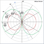
Only at 90 degrees off-axis from an ideal dipole piston will the pressure from the front and rear of the piston be equal and opposite and cancel. At all other angles, the different propagation path distance results in the phase difference being something less than 180 deg for low frequencies and will not cancel. This is what gives rise to the dipole figure-8 radiation pattern you referenced. Phase difference is minimum on-axis(peak SPL) and trends toward a maximum of 180 deg at 90 deg off-axis(Null). If the output is increased be a factor of 2, the SPL at all angles(except 90deg) will increase by 6dB. See Attachment #1.
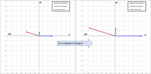
Since your comments were in terms of summation of front and rear radiation, consider an example with a 30cm diameter dipole piston driven at 100Hz and an on-axis listener. The phase difference between the front and rear radiation would be about 165deg. Attachment #2 shows vector summation diaphragm for this example. On-axis summed SPL @ 100Hz is about -12dB lower than for the same piston in an infinite baffle.
- As frequency decreases the red vector will rotate closer to 180 deg, and the summation vector will get smaller by half for each halving of frequency. (ie -6dB/oct slope)
- Similarly, for a given frequency as listener moves off-axis the red vector will rotate closer to 180 deg. (ie dipole radiation pattern)
Instead of summing large number of vectors you could, as golfnut mentioned, use the radiation impedance to calculate the response. The radiation impedance for a dipole radiator has the effect of the front and rear radiation “baked in”. If the radiation impedance is known, it greatly simplifies calculations.
Of course, place this ideal dipole radiator in a room and things get a lot more complicated…wall reflections and room modal behavior contribute considerably to low frequency response at the listening position. But, the output will still scale up and down with input. This means you can equalize the LF response as desired up to the excursion limit of your dipole radiator.
See Page 19.You can read Roger Sanders description of ESL bass suck out in his book here, on pg 18, where he clearly describes the pressure waves from front and back of the panel canceling eac hother out.
“Using an equalizer to increase the diaphragm’s excursion with decreasing frequency is a very effective technique for correcting phase cancellation”
Sanders used equalization in all of his full range designs, and even in his hybrids.
Attachments
…Forever I've been ridiculing cone-drivers air mismatch with "... shaking a heavy piece of cardboard at thin air..." as compared to light-as-air ESLs. But can you or Bolserst provide an everyday tactile analogy to impedance mismatch?
No reason to ridicule cone-drivers. Although the basic transduction mechanism hasn’t changed in 100 years, the EML (Electro-Magnetic Loudspeaker) has evolved from crude “shaking cardboard” to linearly driven nearly perfect-pistons thanks to improvements in materials and motor configuration. Similar improvements in materials and drive configuration evolved the ESL from “flapping pig intestine” to linearly driven, nearly light as air membranes.
Only at the lowest frequencies (more than octave below resonance) does the linearity of the suspension dominate control of the cone motion. For the octave around resonance, damping is dominate. Damping in the EML is provided by the motor. Above resonance the motion of the cone is dominated by the mass of the (cone+voice coil). Since mass is constant, only the motor linearity comes into play. When trying to get an image in your mind of how EMLs and ESLs differ, focus on what controls the motion of the piston(cone for EML, diaphragm for ESL) over the majority of the working bandwidth. With EMLs it is piston mass which is constant. With ESLs it is the airload on the piston which actually varies considerably with frequency.…To generate faithful cone motions you must rely on the motor and bits of rubber and starched cotton to keep the cone assembly from flapping in the breeze irregularly. Nothing is controlling the cone.
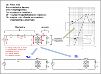
Consider the attached mechanical/acoustic analogical model for a dipole transducer. This is an impedance analogy where voltage represents mechanical force or acoustic pressure, and current represents mechanical velocity or acoustic volume velocity. Again, if we stay focused on the majority of the working bandwidth, the only real difference between the EML and the ESL is the piston mass of the EML represented by inductor Mmd. Note that fc is constant(ie frequency independent) for both transducer types if driven by the typical voltage source amplifer.
- For the ESL, constant motor force (fc) results in constant radiation force (fr), and thus a constant pressure (Po) applied to the airload (ZR+iZX).
- For the EML, since F=ma, constant motor force (fc) results in constant piston acceleration or velocity (uc) that falls -6dB with increasing frequency.
***NOTE: ka=1 represents frequency for which piston diameter is roughly 1/3 wavelength.
Concerning Efficiency and impedance matching:
Impedance matching is important when:
1) you have waves traveling from source to receiver separated by a distance significant compared to wavelength, or
2) when you want to maximize power transfer irrespective of separation distance
However…
1) isn’t relevant to the interface between piston and air
2) maximizing power transfer does NOT maximize efficiency
The concept of maximum power transfer occurring when the impedance of the load matches the impedance of the source can be a source of considerable confusion when efficiency is being discussed.
Maximum power transfer theorem - Wikipedia
For maximum efficiency, you want to maximize the ratio of load impedance to source impedance. In other words, the lower the source impedance relative to the load impedance the higher the efficiency of energy transfer. As golfnut mentioned, the ESL is essentially 100% efficient at transferring drive force to acoustic output. On the other hand, with the EML, the majority of the driving force (fc) is wasted acting on the piston mass(voltage drop across Mmd in the model) leaving only a small portion (fr) to act on the airload. The piston motion is controlled by its mass and the airload is essentially just “along for the ride”.
The above comments address only the efficiency of converting drive force into acoustic output. For overall efficiency, you would also need to consider the power used to create the driving force, which golfnut already covered.
Attachments
Last edited:
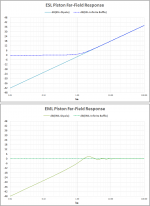
In #2, note EML in a large baffle is potentially capable of flat on-axis response across ka=1No reason to ridicule cone-drivers. Although the basic transduction mechanism hasn’t changed in 100 years, the EML (Electro-Magnetic Loudspeaker) has evolved from crude “shaking cardboard” to linearly driven nearly perfect-pistons ... loadsa good stuff though some of it is perhaps too simplified. .....
Attachment #2 shows the resulting far field on-axis response for EML and ESL operated as dipole pistons, or when placed in an infinite baffle. Let me know if anybody is interested in more details on why they behave this way or how you get these response from the model discussed above.
- For the ESL, constant motor force (fc) results in constant radiation force (fr), and thus a constant pressure (Po) applied to the airload (ZR+iZX).
- For the EML, since F=ma, constant motor force (fc) results in constant piston acceleration or velocity (uc) that falls -6dB with increasing frequency.
Plain Constant Charge ESL can't do this under any practical loading condition. For flat response, you need to invoke Walker/Baxandall ie the CCESLpWB
Of course this only addresses on-axis response but if this isn't flat, you already have serious problems. Along with flat on-axis, you want response off-axis to be sorta flat too ... or at least falling slowly & smoothly. This implies 'flattish' power response across ka=1.
For that, you don't want 'nearly perfect pistons'.
In fact you want a diaphragm which shrinks in size & mass with frequency.I've done a lot with materials, FEA, laser Doppler velocimeters bla bla to achieve this in a 'nice' fashion but the cheapest 3" transistor radio speaker already does it too .. if not as nicely... via cone breakup.
This is what allows a single R&K unit to cover nearly 20Hz - 20kHz .. though you need a big box for the lower limit.What size of unit is optimum for this stupendous 3 decade task? About 6" diameter .. in fact about the size of the original R&K. They got it right from the start.
ESL needs the refinements of Walker/Baxandall to achieve flat on-axis response ... let alone anything similar.
Da true ESL gurus will realise I'm being nearly as simplistic as bolserst. eg no mention of near field. I'm waiting for one to turn up on this thread.
Last edited:
In a loudspeaker handbook I have seen pictures regarding cone breakup and resonance effects.
What can happen is that some parts of the cone move forward and some move backward.
So this resonance is less likely to appear in the output as it cancels. (unless you apply some very local laser doppler measurements?)
But it is resonance energy which needs to be fed from the input signal. As cones are relatively heavy this means you take away energy (information) from the beginning of the exciting signal. So a nearly perfect piston (if it would excist) would avoid this [problem.
In a loudspeaker handbook I have seen pictures regarding cone breakup and resonance effects.
What can happen is that some parts of the cone move forward and some move backward.
So this resonance is less likely to appear in the output as it cancels. (unless you apply some very local laser doppler measurements?)
But it is resonance energy which needs to be fed from the input signal. As cones are relatively heavy this means you take away energy (information) from the beginning of the exciting signal. So a nearly perfect piston (if it would excist) would avoid this [problem.
Acceleration equals force divided by mass.
So if you have more mass, apply more force to get the same acceleration.
Pistonic behavior or not, has to do with stiffness and internal damping of the speakercone/membrane.
Indeed, intentionally simplified to focus on query concerning how impedance matching relates to EML & ESL.... loadsa good stuff though some of it is perhaps too simplified.
Very easy to get lost in the weeds otherwise.
Agreed, and this is exactly what many current DIY builders are doing thanks to golfnut’s AES paper on segmented ESL line sources, and a few software tools.In fact you want a diaphragm which shrinks in size & mass with frequency…ESL needs the refinements of Walker/Baxandall to achieve flat on-axis response
AES E-Library >> Wide-Range Electrostatic Loudspeaker with a Zero-Free Polar Response
experiences with ESL directivity?
Segmented Wire Stator ESL simulator (esl_seg_ui)
Of course there are still tradeoffs between bandwidth, polar/power response, and sensitivity.
Example measurements: Glue for wire stators
Example trade-off trends: experiences with ESL directivity?
Already covered by golfnut in Post #117.…no mention of near field.
ESL driven with voltage source will have flat response in near field.
Pic of ESL-63 dust cover and ragged response posted here:…ESL63 midrange & treble is only OK. The reason is the dustcovers. Fig 6 in Peter Walkers AES article is without dustcovers. Response is MUCH more ragged with.
All Acoustat panels can give
Comparison of measurements vs theory for the effect of dust covers was posted here:
All Acoustat panels can give
The modeling method used is based on techniques described in one of the papers golfnut mentioned in Post #138.
http://www.aes.org/e-lib/browse.cfm?elib=18782
http://www.diyaudio.com/forums/planars-and-exotics/321111-superb-article-hf-esl-phenomena-imho.html
The Toole book provides years of acquired data supporting subjective preference for smoothly trending power/polar response. This highlights the importance of considering directivity when matching up drivers for a system.Sure, for hours on end you can name ways drivers - of all sorts - can match or mismatch as woofers, mids, or tweeters. Yes, there are good and bad drivers. But I can't say as I've ever heard an empirically verified thought on the subject of matching.
Even in the pure ray diagrams, the cancellation is remarkably slight over a large forward angle, as you've illustrated....Only at 90 degrees off-axis from an ideal dipole piston will the pressure from the front and rear of the piston be equal and opposite and cancel. At all other angles, the different propagation path distance results in the phase difference being something less than 180 deg for low frequencies and will not cancel....
But all freq face cancellation albeit at the fluctuating freqs of music (in the pure ideal situation, that can be diagrammed looking like a comb... which is meaningless for shifting tones in music and whether apropos a dipole or off the side walls).
And more, the sound emanates from an extended surface, confusing the cancelation.
And even more, the whole cancellation diagram looks even more like a big bowl of spaghetti when sound comes off the back wall.
B.
Can’t remember if I had mentioned it before, but Edward Kellogg received a patent for the use of LC transmission line in 1934 to minimize amplifier dissipation when driving ESLs. I’m sure Figure 3 looks mighty familiar as the same concept is used in the Quad ESL-63 and decedents. Note also the inverted configuration (for which FINAL was awarded patent US7054456 in 2006) is shown in Figure 1.…Although the ESL itself is efficient, it forces the amplifier to be very inefficient and dissipate high powers.
Attachments
Respectfully, it is evidence of the importance of evaluating the importance of directivity for your setting as illuminated by results in his setting. In any case, not directly speaking to matching.The Toole book provides years of acquired data supporting subjective preference for smoothly trending power/polar response. This highlights the importance of considering directivity when matching up drivers for a system.
BTW, I've been re-examing my youthful exuberance about Toole's studies particularly when intact manufactured speaker systems are used. Specifically, as in medical studies where those folks who eat fish 5X a week seem better than those who eat none. Those two groups of folks differ in many ways, with the parameter nominally under question being only one.
If Toole tested speakers anechoically for, let's say, "clarity" or "airiness", perhaps some of his human preference results would seem to validate those parameters as core to quality as polar results did in the past?
B.
Last edited:
Yup. But what do you think happens on an ESL diaphragm, even a CCESLpWB ?In a loudspeaker handbook I have seen pictures regarding cone breakup and resonance effects.
What can happen is that some parts of the cone move forward and some move backward.
It's NOT a resonance. I've spent a lot of time with our SCAnned Laser Plots (we were the first to do animated laser doppler stuff on speakers) & FEA trying to optimise this behaviour with some success.So this resonance is less likely to appear in the output as it cancels. (unless you apply some very local laser doppler measurements?)
But it is resonance energy which needs to be fed from the input signal.
What you see is travelling bending waves in the cone which cancel out. The 'pistonic' part, which doesn't cancel out, has 'bulk' waves where the speed of sound is much higher. In a well behaved cone, this part shrinks nicely with frequency.
Resonances give stationary bending waves and you can sometimes see these on simple impedance plots too. The waves have to be terminated properly.
That's with a good sounding engineered plastic cone.
Ted Jordan had several 1960 & 70s (?) articles in Wireless World about this. His ideas were sorta right but his detail was seriously wonky. He didn't have laser Doppler velocimetry & FEA.
The breakup behaviour of a good sounding paper cone is very different though you still have this shrinking central 'pistonic' part.
A 'nearly' perfect piston' operating across ka=1 sounds terrible. We tried this with Berillium and also a ceramic material. It's only useful in certain treble units. I still prefer a soft dome ... though we designed some of the best hard dome trebles in large scale production.So a nearly perfect piston (if it would excist) would avoid this [problem.
Good sound in a speaker is more than some fashionable buzz word like 'pistonic', ESL, directivity, Room Interface Profile bla bla. In the end, you need to 'measure' the sum of all da bits to see if you get 'good sound'. You do this with DBLTs
...Good sound in a speaker is more than some fashionable buzz word like 'pistonic', ESL, directivity, Room Interface Profile bla bla. In the end, you need to 'measure' the sum of all da bits to see if you get 'good sound'. You do this with DBLTs
Say kgrlee, wouldn't it be nice to let the rest of us see what DBLT is all about even if we don't want to pay $30 for the treat as per your earlier link? Your cherished method seems to have escaped the attention of the rest of the world, at least so far.
You allude to a speaker business. Without fussing about mixing subliminal marketing and pleasure at this website, it would be helpful to learn just what products you are so very proud of?
Please do not mistake my flippancy for anything but sincere interest in the research and results you talk about.
B.
What is your point Ben? Are you claiming matching directivity across a xover is unimportant? Are you one of those who believe speakers (& stereo) will sound so better in anechoics?Respectfully, it is evidence of the importance of evaluating the importance of directivity for your setting as illuminated by results in his setting. In any case, not directly speaking to matching.
The BBC have tested both these points since the early 70s or even earlier. Wanna guess the results?
I have serious reservations about how the false prophets Floyd & Olive conduct DBLTs. But at least they reference & confirm our work on AUDIBLE SPEAKER DISTORTIONS
What is your point Ben? Are you claiming matching directivity across a xover is unimportant?
As a sort of summation of his book, Toole argued that excellent polar plots (in 3D!) are very important to good SQ. Who could argue with that, at least in the abstract?
And maybe "matching" is an unhelpful term. Maybe "what tweeter should I buy, all things considered" is a better term. In that sense, all kinds of things might occur to the builder with dovetailing polar plots being only one. Not that there is any indisputable way to define "dovetailing" of two fuzzy curves families (in 4 dimensions because you have to count freq), a fact that kgrlee seems to overlook.
But to someone who is a commercial partisan, sometimes only one leading patentable feature like matching dispersions at the crossover point might seem to matter.
B.
- Home
- Loudspeakers
- Planars & Exotics
- Electrostats vs conventional drivers