I’m using magnet wire to build wire stator based electrostatic speakers. The wire, including its heavy build nylon insulation, has a diameter of 0.55 mm (0.022”). I’m going to try to work with a 1 mm gap between the stator wires and the diaphragm, although I can increase that if I it turns out I can’t maintain small enough tolerances to make 1 mm work. My real issue is that I’m trying to decide on the spacing between wires (meaning between wires in the same stator). By the way, I'm planning on limiting the ESL panel to frequencies above about 250 Hz or so. I'll fix the exact crossover frequency once I see how the panels behave.
My original plan was to use a 1 mm center-to-center wire spacing. To achieve this, I was going to use two pieces of threaded rod with 2 mm thread pitch, one piece at each end of the stator, wrap the wire between the rods, and use the threads to establish a consistent spacing. I was then going to use pieces of threaded rod with 1 mm pitch to push down on the wrapped wires to force them to lie in a plane and stabilize their 1 mm center-to-center spacing.
If my arithmetic is right, this approach would give me 0.45 mm of air space between wires, and a 45% open area. As I look at some quick mock-ups, it sure looks like very close wire spacing. I like the 45% open area value—I wanted to end up on the small side of 50%-- but am I at risk of having too small a gap between wires?
I could switch to using threaded rods with 10 and 20 threads per inch in place of the 2 mm and 1 mm pitches, respectively. That would increase the center-to-center spacing of the wires to 1.27 mm (.050”), increase the gap between wires to 0.72 mm, and increase the percent open area to 57%. That percent open area is larger than I wanted but somehow it looks better by eye.
Another reason I wanted to go with the 1 mm spacing is that I didn’t want the wire spacing to be large compared the stator-to-diaphragm distance. I guess the gap would be less than 1 mm in either case, so maybe that’s not really an issue.
So my reason for posting is to get a reality check. Do I go with the initially planned 1 mm center-to-center spacing (45% open area) or modify my set-up and go with 1.27 mm (0.050”) center-to-center spacing and 57% open area? I can post photos later if seeing the wire stretching jig would make it easier to judge. Thanks in advance.
Few
Well, if you hear with your eyes...
but if not, I think you better go for efficiency, even 35% open area would be enough. Because of the low distortions coming from ESL's (~1/5 of dynamic LS's) you want to listen louder. And as a benefit, your transformer does not need to be very big.
Regards
Frank
but if not, I think you better go for efficiency, even 35% open area would be enough. Because of the low distortions coming from ESL's (~1/5 of dynamic LS's) you want to listen louder. And as a benefit, your transformer does not need to be very big.
Regards
Frank
Thanks Frank. I agree that aiming for a percent open area lower than 50% makes sense. I guess my real question is, for a given open area percentage--let's say 40% just for discussion--is it possible to use wire gaps or perforation holes that are too small?
I think it's clear that it's possible to use gaps or holes that are too large. If the holes are large compared to the stator-diaphragm distance then all points on the diaphragm may not experience the same electric field strength.
The question I've run into is whether it is possible to make the holes so small that air flow as adversely affected, even if the open area is sufficient.
One of the reasons I went for the small wire and small gaps to begin with was that I know some builders end up adding some fibrous material behind the rear stator to damp the fundamental diaphragm resonance. I figured it made more sense to achieve the damping by using a stator with small gaps or holes because you might pick up some helpful efficiency (sensitivity) in the process. But those small gaps or holes will be between the diaphragm and the listener as well. Do they just act as a helpful acoustic resistance, or is there a risk of turbulence or other ill effects that might interfere with the clarity of sound?
Have had good results with...
using 30 gage magnet wire 24 wires per linear inch. I use a 24 thread per inch threaded rod as a guide. More wires per inch provides higher field stength and the lower open area provides resistive acoustic damping to the diaphragm. Have attached a picture not great quality but should give ou an idea. hope this is of some use.
using 30 gage magnet wire 24 wires per linear inch. I use a 24 thread per inch threaded rod as a guide. More wires per inch provides higher field stength and the lower open area provides resistive acoustic damping to the diaphragm. Have attached a picture not great quality but should give ou an idea. hope this is of some use.
Attachments
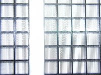
Thanks, Moray James, for the information and photos. It's helpful. Your photo seems to show considerably more open area, compared to the wire diameter, than what I've got planned. What's the percent open area for the stators you showed in the photos?
Here are a few images of my wire stretching system, in case they're helpful. First a couple of shots of the 2 mm pitch threaded rods in the wire stretching system, along with one of the stator frames that will support the wire. The frames are made out of paper based phenolic. I bought the material from McMaster-Carr, who calls it Garolite. The 1 mm pitch threaded rod is hard to see in these photos. It's attached to the bottom of the vertical piece of plywood that's parallel to the 2 mm pitch threaded rod.
The next two images show the phenolic frames from other perspectives. The spring clamps are in place because I was actually using epoxy to attach the cross-members to the wider pieces of the frame. The two long sections of magnet wire under the cross-members are used to space the cross-members uniformly from the lower surface of the wider frame pieces. In the next stage of construction the stretched magnet wires will be glued in place so that they end up flush with the lower surfaces of the wide frame pieces--in other words, the lower surfaces of the wide phenolic pieces and the lower surfaces of the magnet wire surfaces will lie in the same plane.
I'm not sure I've described this clearly, but maybe the photos will clarify the situation somewhat.
Few
Few
Here are a few images of my wire stretching system, in case they're helpful. First a couple of shots of the 2 mm pitch threaded rods in the wire stretching system, along with one of the stator frames that will support the wire. The frames are made out of paper based phenolic. I bought the material from McMaster-Carr, who calls it Garolite. The 1 mm pitch threaded rod is hard to see in these photos. It's attached to the bottom of the vertical piece of plywood that's parallel to the 2 mm pitch threaded rod.
An externally hosted image should be here but it was not working when we last tested it.
An externally hosted image should be here but it was not working when we last tested it.
The next two images show the phenolic frames from other perspectives. The spring clamps are in place because I was actually using epoxy to attach the cross-members to the wider pieces of the frame. The two long sections of magnet wire under the cross-members are used to space the cross-members uniformly from the lower surface of the wider frame pieces. In the next stage of construction the stretched magnet wires will be glued in place so that they end up flush with the lower surfaces of the wide frame pieces--in other words, the lower surfaces of the wide phenolic pieces and the lower surfaces of the magnet wire surfaces will lie in the same plane.
I'm not sure I've described this clearly, but maybe the photos will clarify the situation somewhat.
Few
An externally hosted image should be here but it was not working when we last tested it.
An externally hosted image should be here but it was not working when we last tested it.
Few
Off the top of my head ....
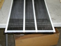
I would say that the open area is probably about 33% don't quote me but it's in that ball park it might be a littl less, I have been considering 32 wires per inch. The cubes in frame I showed are 1/2 inch square. Have atached a picture of half a panel which is a three section two way
I would say that the open area is probably about 33% don't quote me but it's in that ball park it might be a littl less, I have been considering 32 wires per inch. The cubes in frame I showed are 1/2 inch square. Have atached a picture of half a panel which is a three section two way
Attachments
That's interesting Frank...
could you comment further or do you have any references to studdies? David Lang published in Speaker Builder and showed some unexpected results with perf metal being more efficient than aluminum insect screen with 1/16 inch spacing.
The advantages of wire are simple segmentation and mil spec dielectric along with low wire cost when compared to perf metal and powder coating.
Few was talking about holes,
and I did not mean electrostatic forces, I meant air.
Holes are like little Helmholtz resonators, so the smaller and
longer (thicker the perforatet Plates) holes are, the bigger the
acoustic resistance. Wires are different, because they are round...
Regards, Frank
and I did not mean electrostatic forces, I meant air.
Holes are like little Helmholtz resonators, so the smaller and
longer (thicker the perforatet Plates) holes are, the bigger the
acoustic resistance. Wires are different, because they are round...
Regards, Frank
Thanks for the continued input. I've often wondered about the notion that holes with diameters of a millimeter or two will act like Helmholtz resonators with frequencies pertinent to an audio system, but maybe you have to think in terms of collections of holes, rather than individual ones. In any case, I agree that's not likely to be much of an issue with the stretched wires.
Just from Moray James's photo I would have guessed an open area over 50% but it's hard to say with any confidence. MJ: What's the diameter of the magnet wire in those photos? My table of wire gauges suggests 30 gauge wire has a diameter of 0.25 mm but that won't include the insulation. If there are 24 wires per inch, that's a center-to-center spacing of 1.06 mm. If we neglect the fact that we're missing the insulation, the open area would be about 76%. Obviously that number will drop when the insulation is taken into account, but will it drop by more than a factor of 2? Am I doing something stupid with my arithmetic?
I'm still wrestling with this question of whether overly small wire gaps are going to "muddy" the sound and would welcome further help.
Few
- Status
- This old topic is closed. If you want to reopen this topic, contact a moderator using the "Report Post" button.
- Home
- Loudspeakers
- Planars & Exotics
- wire spacing for stretched wire ESL?