This is the mid section
Go slow and rock back and forth slightly as the exposed glue lines want to stick to the upper rod and a slight tug releases it
A note to be made as the panel did start to go out of alignment , and all you have to do is start pulling on that side and it will come back as you continue rolling.
You cannot tell in this photo as I had corrected it a few inches back
Attachments
Last edited:
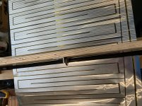
So here I am in 6 feet , and the top section of the foil and alignment is still parallel to the rollers
It is quite easy as you go , to keep it in alignment by gently pulling as mentioned
No need to panic here !
In retrospect , 2 roller sections equally spaced would be better overall I believe and lessen hand alignment but still easily solved
I will be making the first panel over as this one turned out better. That Kapton crease on the back and some of the open trace edges were not as good as this one . Going slower and rocking bk and forth made for a better finished panel
So I hope you will give it a go !


Regards
David
It is quite easy as you go , to keep it in alignment by gently pulling as mentioned
No need to panic here !
In retrospect , 2 roller sections equally spaced would be better overall I believe and lessen hand alignment but still easily solved
I will be making the first panel over as this one turned out better. That Kapton crease on the back and some of the open trace edges were not as good as this one . Going slower and rocking bk and forth made for a better finished panel
So I hope you will give it a go !
Regards
David
So here I am in 6 feet , and the top section of the foil and alignment is still parallel to the rollers
It is quite easy as you go , to keep it in alignment by gently pulling as mentioned
No need to panic here !
In retrospect , 2 roller sections equally spaced would be better overall I believe and lessen hand alignment but still easily solved
I will be making the first panel over as this one turned out better. That Kapton crease on the back and some of the open trace edges were not as good as this one . Going slower and rocking bk and forth made for a better finished panel
So I hope you will give it a go !
View attachment 796354
View attachment 796355
Regards
David
that looks really slick !!! nice work !!! im no fan of kapton

The motor idea is unnecessary as you need to rock the wheels in each groove as the valley is wider than the peak profile and this rocking makes sure you cover the area completely.
This gives the ripple better uniformity
You also have to be careful of each open glue area as it sticks inconsistently and requires some TLC as you go.
Regards
David
This gives the ripple better uniformity
You also have to be careful of each open glue area as it sticks inconsistently and requires some TLC as you go.
Regards
David

On the second panel I used this to check Diva magnet spacing.
It allows you to spot which magnet row is off if any. There were 3 rows slightly off in random spots
This spreads to 13” and I got between 1.281” to 1.300” ( Ctr. To Ctr. ) variations in each section
and made the panel to match exactly each section area
Total top to bottom magnet spread center to center Diva magnet spacing is 64 1/4”
Pulling magnet rows and moving them around was something I didn’t want to mess with
Regards
David
I have no idea what that is, but I want one!
Two thumbs way up here on what you are doing. I'd have caved in and paid for someone to do the job long before this point!
Hello! I have a pair of late Diva's, never used. Been in a warehouse all these years and during those days right bass panel was lightly damaged. Corrugations have opened at the bottom (I will include few photos if I can figure out how?). Panel itself (aluminium & kapton) is intact, just the corrugation is slightly damaged. I've been been thinking the right way to fix it, just wondering, if a heating of somekind would do the trick? Any suggestions?
You will most definitely make things worse if you start working on to fix the membrane. It's extremely delicate. The membrane is glued on the mdf fixing bars. If you take the membrane off even a little, the right tuning/tension is lost. I would just leave it as it is.
Ok, thanks for the advice. If I remember right the up and bottom bars are not glued to the membrane, just the sides (that was the thing where I did put my hope to). And in my opinion the tension is horizontal, not vertical. Vertical "tension" is caused only by corrugation, and that's exactly the thing what I'm trying to fix now. Surely I don't mess with it, if it seems to be glued, I leave it as it is.
-Anssi-
You mentioned these were new and never used, but 30 years have gone by and more than likely the dreaded foam issue lurks underneath.
When you pull off the unglued bottom clamp you will get an idea of its foam since its the same material as the vertical strips that encompass both sides of the panel.
When you pull off the unglued bottom clamp you will get an idea of its foam since its the same material as the vertical strips that encompass both sides of the panel.

The corrugated rollers I made for this earlier in the posts reduce the total dimension 3/4” if you match the total dimension center lines of the top and bottom magnets (64 1/4” Diva panel)
This 3rd flat panel I cut matched this dimension and had to stretch it vertically for line up a little more than I liked, so a little bigger overall dimensions are called for if you use these particular rods.
Figure a 1/4” more over the 64 1/4” dim. so it means your only stretching vertically a 1/2” instead of 3/4”
Its a delicate toss up on how much to allow on whatever corrugation method you use.
I would suggest making a couple of test pieces say 2 foot long to get an idea of how much it takes to keep it in alignment because of the shrinkage issue
- Home
- Loudspeakers
- Planars & Exotics
- Anyone making Apogee bass panels?