I guess the extra layer of coating would make things worse instead of better. Extra thickness is extra weight. So in theory it would take the diaphragm more time to come to a stop and make it slower to respond. And I agree with MJ Dijkstra it would have a bad effect on higher frequency response. The damping as it was designed by Peter Walker is done by the mesh on the rear stator. Be aware that some people abuse this mesh by obstructing a large amount of the mesh with glue in an attempt to better fix the stator without removing and reapplying the stator. They just drop a big amount of glue along the ribs of the ABS frame on top of the stator. That will affect the damping as intended because less air can pass through the mesh. I also think that the thick "damping" coating will kill the effect of the delay lines which are crucial in creating a 3D sound image and creating the virtual point source. Pulse will be affected in a negative way. The total thickness of Mylar and both coatings sum up to 10-12 micron. I can't think of any positives.If the coating has damping properties why is the cumulative spectral decay of a quad not better than lets say audiostatic? According to measurements done by Stereophile (take a google search) the ES100 does a better job than Quad 2805 regarding the CSD plot. Maybe the CSD plot was much worse if the Quad had not this 'damping' coating, we only can find out when measuring an original panel against a panel with new Mylar without damping......
I also think there are better ways to kill spurious resonances and such thick coatings only degrade high freq. response (quad rolls off at high freq.....)
Attachments
My cheap surface resistance meter arrived yesterday, I've not had chance to check the accuracy of the reading yet, it has proved a bonus in not tearing the membrane though.
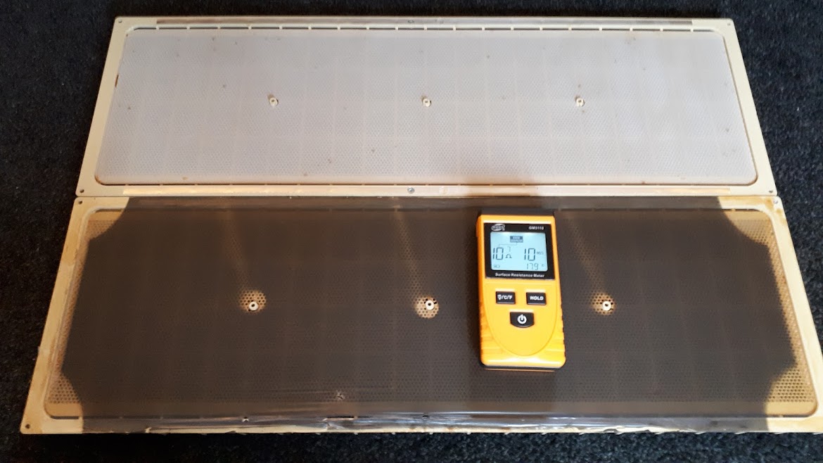
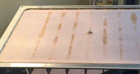
A broken panel from old 63's, S/no 1692 with 2 part coating showing a surface resistance of 10^6/10^7.
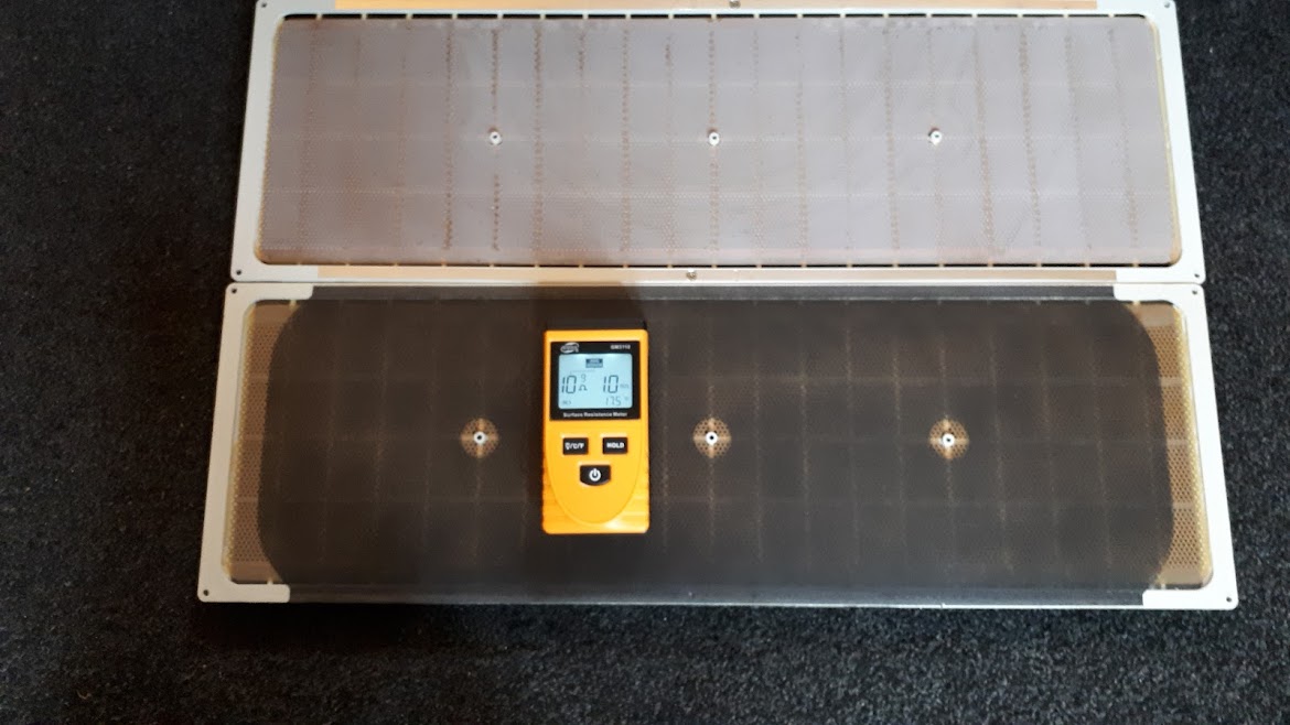
A 'new' panel as fitted by Quad at Huntingdon March 2014.
Surface resistivity 10^8/10^9. 1 part sprayed coating with convex corner pattern, damping mesh to rear stator is a mauve colour.
A broken panel from old 63's, S/no 1692 with 2 part coating showing a surface resistance of 10^6/10^7.
A 'new' panel as fitted by Quad at Huntingdon March 2014.
Surface resistivity 10^8/10^9. 1 part sprayed coating with convex corner pattern, damping mesh to rear stator is a mauve colour.
Last edited:
I don’t think the coating has much if any effect on the CSD (just not an effective way to damp diaphragm modal behavior), and you are absolutely right about the added mass degraded the HF response.If the coating has damping properties why is the cumulative spectral decay of a quad not better… such thick coatings only degrade high freq. response (quad rolls off at high freq.....)
What the damping coating DID do was reduce the crinkly noises that the mylar makes when you handle it. If the crinkly nature of mylar adds a coloration to the sound, this damping coating would go a long way toward eliminating it.
What the damping coating DID do was reduce the crinkly noises that the mylar makes when you handle it. If the crinkly nature of mylar adds a coloration to the sound, this damping coating would go a long way toward eliminating it.
Crinkly noises.....you mean that is like the Mylar ads sound which is not present in the original signal? I presume such colouration would show up in the CSD-plot as a ringing signal......
Maybe there is simply no good reason for adding this stuff.....or it is with a good idea in mind but not supported by evidence.....
Crinkly noises.....you mean that is like the Mylar ads sound which is not present in the original signal?
It does if the dust covers loose tension (drumming). Or the panel membrane.
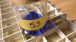
My last testing is with coating test number #353 (I'm mixing and testing for 3 years now)
As I wrote in earlier posts I'm now testing with different humidities. This last coating has a blink interval of several minutes at humidity 50%. The interval is 15 seconds at 65% humidity and 2 seconds at 85%. So although the blink interval is much much longer at normal humidity levels than with my earlier coating, I cant improve the interval between blinks at the 85% humidity level. So I leave it at that. As I mentioned before the humidity in my country hardly ever reaches 70% and mostly it is between 40% and 55%. The thickness aof the Mylar with the coating is 4 micron and the weight is 6 grams/m2 both measured with my cheap China made scale and thickness meter. It is a PEDOT based coating hence the colour blue.
Now on with further testing on sound, SPL, sensitivity for spark damage, durability etc.
Attachments
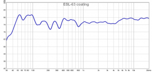
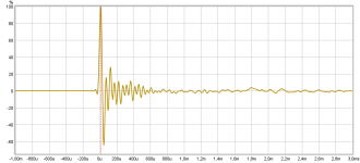
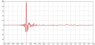
Here are the first measurement results of the ESL-63 with the latest test coating applied. Measurements done with REW version 5.20 with the MiniDSP UMIK-1 microphone with calibration file at 1 meter in front of the speaker. Just done in my living room, so no acoustic dead room! The frequency graph is smoothed with 1/6. The pulse is a 4 ms window, from -1 to +3 ms. It looks pretty good to me, but remarks are always appreciated.
My interpretation:
Frequency: 40 Hz to 20 kHz within +3 dB and -6 dB and very strong in high frequency region in comparison to charts I've seen from Audiophile tests.
Pulse: Total silence within 500 micro seconds and very symmetrical reverb
SPL is measured to be 84,1 dB which I think is still a little too low
Distortion numbers are 0,15% on average
Attachments
Last edited:
Yes, as misterdog mentioned, loosely stretched mylar will add obvious extraneous noises when generating sound. The crinkly noises I mentioned are what most people experience when handling a loose piece of mylar, waving it around in the air. The Quad mylar with the damping coating on it is noticeably quieter when waving it around. The question is, does this translate into improved fidelity with a properly stretched diaphragm. I don’t know as my limited comparisons have been inconclusive, which was why I used the word “if” in my previous response. It may be as you state, a good idea in mind (ie it damps noises when unstretched so must be beneficial when stretched as well), but not supported by evidence.Crinkly noises.....you mean that is like the Mylar ads sound which is not present in the original signal? I presume such colouration would show up in the CSD-plot as a ringing signal...Maybe there is simply no good reason for adding this stuff...or it is with a good idea in mind but not supported by evidence.....
If ozone is the cause of the odd diaphragm damage, the question then becomes why is ozone generation a problem with this particular coating and virtually no others?There is no need for ark(ing) per say to produce ozone. It's called DBD and is caused by displacement current through dielectric/isolator.
Hmmmm…. Doesn’t there need to be a dielectric-to-air boundary for the ozone to be generated? If so, are you suggesting there may be air trapped between the coating and the diaphragm?
Let's assume dielectric coated plate i.e. stator, actually two of them separated by a distance. AC voltage is applied and the displacement current will flow through a pair of stator like in any other capacitor. Explanation given in literature is kinda peculiar. Anyhow it's assumed that at a particular spot at dielectric surface enough charge accumulates to provide enough field strength to generate small strimmer and subsequently tiny ark. It can discharge into the air or as it's usually said volume. Discharge current can be measured. On a scope it looks like vertical needles on a sinewave. Short wavelength light from plasma excites oxygen thus generating ozone. Substantial amount of nitrogen dioxide is also produced.
It's really hard to catch unless you have a lot of discharge instances due to very short duration.
An finally answer to your question. You have the boundary between two electrodes. And you do have dielectric coating on the ones to prevent straight breakdown. One method to decrease ozone generation is to reduce current density trough the "capacitor" I=dQ/dt and I=C*dUc/dt. Second one would be to remove air(gas) per say.
However some believe that charge accumulates on a tiny water paddles on a dielectric surfaces. It could be that semiconductive coating on dielectric or semiconductive dielectric itself would help. That's said its remarkably easy to create barrier discharge: just apply high enough AC voltage between the plates Higher permittivity dielectric helps a lot, with barrier discharge of coarse.
Suggestion. Take a pair of coated plates (stators) like 4x4" in size connect to the secondary of a transformer, put a current sensor(resistor) in cold (grounded) end and observe the current. At some voltage you will hear a particular hissing noise and pinkish, in my experience, glow. The latter is not bright but you do not need total darkness. At the same time you will observe needle like current waveform. it might not work with low bandwidth scope - mine was like 200MHz.
Now you know what is the voltage limit. Hope this helps.
Alex
Last edited:
Statclear A50
Hi,
Thought this would be of interest to this thread,
Statclear and ESL Audio Speakers - Electroguard Anti-Static Paint
Hi,
Thought this would be of interest to this thread,
Statclear and ESL Audio Speakers - Electroguard Anti-Static Paint
I also had contact with Electroguard and bought Statclear 50 to test in September 2017. My conclusion was that the resistance was too low for my ideas (please note this part! This is what I think), only 10^6 - 10^7. I requested if they could up the resistivity for better purpose on an ESL. I always ended up with 10^7 and never with 10^9 as the advertised upper limit.Hi,
Thought this would be of interest to this thread,
Statclear and ESL Audio Speakers - Electroguard Anti-Static Paint
This was the answer they gave me:
Jos,
Thank you for your enquiry on Tuesday. We played around with the formula yesterday, adding more water, reducing the conductive element etc but unfortunately we can not alter it. The conductive aspect is inherently around 10^7-10^9 and it does not alter. It is either there at that level or we reduce it so much that it becomes insulative. It is quite a black or white product, we can not alter it on a controllable sliding scale.
I am sorry that we can not help further.
Regards, Neil Woods
Hi,
Thought this would be of interest to this thread,
Statclear and ESL Audio Speakers - Electroguard Anti-Static Paint
I saw this posted on FB and my questions were " How much does this coating cost and is it available here in the states?" .
jer
")
The price was € 40,00 per 500ml back then. That would be something like $ 45,00 per bottle. Wasn't easy to find a distributor that sold one bottle. Most of them wanted only to sell per box of 12 bottlesI saw this posted on FB and my questions were " How much does this coating cost and is it available here in the states?" .
jer
. Don't know if they have a representative in the US, but just drop them a line they are very helpful.Thank You for the info !!
It is about the same as Licron then.
Although the Crystal version has a much higher resistance than the old Licron version, I do have a use for a staticide that is in that range of resistance since the original Licron formula is no longer available.
cheers !!
jer
It is about the same as Licron then.
Although the Crystal version has a much higher resistance than the old Licron version, I do have a use for a staticide that is in that range of resistance since the original Licron formula is no longer available.
cheers !!
jer
Hi,
Thought this would be of interest to this thread,
Statclear and ESL Audio Speakers - Electroguard Anti-Static Paint
I particularly enjoyed the quotes for the ESL builder on the site:
“I have been designing and building electrostatic speakers for about 35 years now, and one of the problems is maintaining a slight conductivity of the coating on the diaphragm in the order of 50 to 200M ohms (50×10 (6) , 200 x 10 (6) per unit area over long periods of time (years) and I have tried everything from liquid ivory soap to chimney soot and many potions in between."
And what potions would be in between those two? Old bacon grease? Maybe some pond water? Lord son, go find a chemist. There's a zillion possibilities out there now that ESD is an issue in our lives. He needs a binder that sticks well to PET.
“Conductive coating is one of the most important elements affecting the sound quality and reliability of electrostatic loudspeaker. "
Sure, that's very true when your coating is the weakest link. But in a normal ESL I don't find that statement to be true at all. The coating has two jobs, the first one is to stay in place, which is actually pretty easy in this world of polyester resins for the printing and other industries. I use a polyester resin that is also used in cosmetics as well as a variety of other industrial products. The second thing that the coating needs to do is be slightly conductive. That's pretty easy as well, there's a ton of powders available out there as mix-ins to make coatings and bulk materials slightly conductive for ESD packaging.
Once you have a binder and a conductive filler, you will probably need a dispersant to keep the filler from clumping. A wetting agent might also be needed depending on the surface tension of your components. Then it's a matter of trying different filler concentrations to dial in your desired conductivity. There's some other subtle issues like pH and storage ability etc. But it's not hard to come up with a nice workable coating.
BTW, I've measured a lot of Quad ESL-63 (and newer) panels, and with my gimpy conductivity meter, they all measure about 10^7 ohms/sq. So that stuff would probably work quite well with any of the modern quads.
Sheldon
I would add to this having a low mass, aiming at a mass which corresponds to about 1 um Mylar max. This is of little value in ESD packaging but it is in ESLs. You also want the resistance not to be affected by airhumidity, specially when you have a high resistance coating getting close to the order of magnitude of the leakage resistance. Some would also like the coating being transparent not opaque for esthetic reasons.
- Home
- Loudspeakers
- Planars & Exotics
- ESL Diaphragm coating