That's great. It seems you have good driver support for your onboard audio hardware (unlike me!) ...As can be seen, I have 4 Sample Rate options, from 44.1KHz to 192KHz..
but don't assume success until you actually play a 192kHz audio track - and you can see the "192" LED displayed on your DAC - this is the final measure of success.
It would also be good if your driver can auto-change the output sample rate. Let's say that you configure the driver for 192kHz output. When you play 192kHz tracks all is fine, but when you change to a 44.1kHz track if the output stays at 192kHz then your playback application (or some other link in the chain) will need to perform sample rate conversion. Some people claim that up-sampling is a good thing, but it's certainly arguable, especially if the up-sampling is not a neat integer value.
Yes, as I mentioned in post #2, 2nd line.Tas1020B with appropriate firmware can play max 24bits/96kHz.
Yes, as I mentioned in post #15, 1st paragraph.CMedia CMI9761A is an AC97 codec capable of 96kHz http://pdf4.datasheet.su/236123.pdf . A question is whether your onboard AC97 controller also supports 96kHz, and whether the WinXP driver supports that. Very likely not.
Regarding my AV710's Toslink output, yes, I'm aware that only certain models of optical s/pdif transmitter - such as the Toshiba TORX147 - support 192kHz, but under Linux I couldn't even get 96kHz output. I'm using an old version of Puppy Linux, which is a minimalist Linux distro with ALSA, and does not include PulseAudio. Ironically, I have read that it may be possible to (more easily) configure s/pdif output sample rate with PulseAudio - via /etc/pulse/daemon.conf
Maybe I just need to run a Linux with PulseAudio? But it's annoying that I can't configure ALSA for 96kHz s/pdif output.
No. The s/pdif header on your motherboard (and mine) is coaxial, only.So the same pin header on the motherboard can be used either for Optical or Coaxial..
It's worth noting that there's nothing special about a s/pdif-out panel - you could just as easily wire up a cable from 2x header pins to RCA connector - that's what I did. Pin 1 is signal, pin2 is GND.I will report immediately after receivng and installing the SPDIF-Out panel.
HQ-Audio DAC-END R, by Quang Hao and Andrea Ciuffoli.BTW, what is your ES9018 DAC?
ES9018 USB DAC - Hi-Resolution System
The CS4398 DAC chip in the SMSL M3 supports samplerates up to 192kHz, but 192kHz can only be realised using the s/pdif interface.
The M3's TAS1020B USB interface supports a maximum samplerate of 96kHz.
.
I have done a bit with USB interfaces.
USB can be quite slow despite mega bit speeds.
I have also had problems with fast USB speeds dropping out on my modern PC.
I find I have to revert to slower speed for my USB scope interfaces.
While the fast USB speeds work with flash cards in the back of the PC they can start to fall apart with 2 or 3 metres of cable.
but under Linux I couldn't even get 96kHz output.
I have worked with many ice1724 cards, written/fixed alsa support for a few (Juli, Quartet, Prodigy192), I dare to say I know the ice1724 chip and driver quite well. The controller has a single clock and the rate of the SPDIF output is the same as the rate of the other outputs. If the analog channels run at 192kHz, the SPDIF will run at that too. Some cards offer only 96kHz (stored in their eprom or hard-coded in their respective driver).
If your playback chain allows only 48kHz, you are accessing your ice1724 device through some mixer, be it dmix or pulseaudio. Direct access (hw:X) will give you full speed, analog or spdif, the same processing by the controller.
Or you may have the "Multi Track Rate Locking" control enabled in which case the ice1724 driver will not allow you to choose a different samplerate. It is a bit unusual feature which I have not found a use for. By default it is disabled. You would see that in alsamixer/amixer.
Thank you, I will check that once the Panel arrives..It would also be good if your driver can auto-change the output sample rate. Let's say that you configure the driver for 192kHz output. When you play 192kHz tracks all is fine, but when you change to a 44.1kHz track if the output stays at 192kHz then your playback application (or some other link in the chain) will need to perform sample rate conversion. Some people claim that up-sampling is a good thing, but it's certainly arguable, especially if the up-sampling is not a neat integer value.
So the same pin header on the motherboard can be used either for Optical or Coaxial..
Nice to know that.
Hmm,No. The s/pdif header on your motherboard (and mine) is coaxial, only.
It's worth noting that there's nothing special about a s/pdif-out panel - you could just as easily wire up a cable from 2x header pins to RCA connector - that's what I did. Pin 1 is signal, pin2 is GND.
Is there an electrical difference bewteen the signal for SPDIF Out Coaxial and SPDIF Out Optical?
If you say that the SPDIF Out header on mine and your motherboard is coaxial only,
then it means that the panel that I bought does something in addition?
I imagine a coaxial output may need little more than an output transformer, if that (the signal out of the mo/bo may or may not be at 75 ohm level and ready to use), while an optical out definitely requires a typically +5V supply to feed the optical transmitter.Is there an electrical difference bewteen the signal for SPDIF Out Coaxial and SPDIF Out Optical?
Thank you, I will check that once the Panel arrives..
Hmm,
Is there an electrical difference between the signal for SPDIF Out Coaxial and SPDIF Out Optical?
If you say that the SPDIF Out header on mine and your motherboard is coaxial only,
then it means that the panel that I bought does something in addition?
The digital signal on pin 1 is coded using the 'biphase-mark-code' (BMC). Assuming the voltage level is 3.3 volts, on (high) is 3.3 volts, off (low) is zero volts. This could be verified using a DMM. Since the voltage is on about half the time and off half the time, you will get a measurement of 1.65 volts between pin 1 and ground. This can be fed directly to a DAC (coaxial), although the voltage "should" be reduced using a voltage divider.
For toslink, the on voltage triggers the toslink transmitter to light up the led. At zero volts, the led goes dark. Yes...the led blinks millions of times per second. However, the toslink transmitter requires 5 volts to power the led. The s/pdif header on my motherboard has three pins with 5V on the third. If the panel you purchased has toslink it will need to be supplied with 5V if you want to connect via toslink. Hopefully there is a 5v pin on the motherboard your can tap into.
I think I have this right.
Mike
Thank you very much to both of you.
So allow me to refine the question:
I understand that SPDIF-Out Coaxial is a 3.3v Signal,
while an SPDIF-Out Optical Transmitter component requires being fed with a 5v Signal.
But is the signal identical on both Coaxial and Optical, apart from the different voltage?
So allow me to refine the question:
I understand that SPDIF-Out Coaxial is a 3.3v Signal,
while an SPDIF-Out Optical Transmitter component requires being fed with a 5v Signal.
But is the signal identical on both Coaxial and Optical, apart from the different voltage?
Thank you very much to both of you.
So allow me to refine the question:
I understand that SPDIF-Out Coaxial is a 3.3v Signal,
while an SPDIF-Out Optical Transmitter component requires being fed with a 5v Signal.
But is the signal identical on both Coaxial and Optical, apart from the different voltage?
Yes, the digital signal is identical. For coaxial, the 0 - 3.3v square waves are carried end-to-end. For toslink, the 0 - 3.3v square waves are converted to led off/on pulses, then the off/on pulses are converted back to 0 - 3.3v square waves on the receiving end.
Mike
3.3v for Toslink?Yes, the digital signal is identical.
For coaxial, the 0 - 3.3v square waves are carried end-to-end.
For toslink, the 0 - 3.3v square waves are converted to led off/on pulses, then the off/on pulses are converted back to 0 - 3.3v square waves on the receiving end.
We have just said 5v, no?
(the Optical Transmitter requires a 5v Signal)
3.3v for Toslink?
We have just said 5v, no?
(the Optical Transmitter requires a 5v Signal)
The transmitter requires a separate 5V power supply for the led circuit. This circuit converts the 3.3v input digital signal to light pulses.
Sorry if this isn't clear. I assume you are getting something like this?
SPDIF optical and RCA out plate cable bracket for asus msi gigabyte motherboa ZT | eBay
As you can see, it has three connections... +5 volts, ground, and the S/PDIF signal (the 3.3v square waves).
Mike
In that sound card configuration program, in the "Audio IO" tab,
If I click the top ComboBox which displays "2CH Speaker",
I can choose "4CH Speaker" or even "8CH Speaker"..
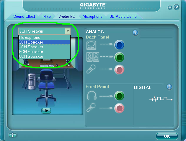
I wonder If I change it from 2CH to 4CH for example,
how do I connect the additional (rear) 2 speakers to the sound card?
If I click the top ComboBox which displays "2CH Speaker",
I can choose "4CH Speaker" or even "8CH Speaker"..
I wonder If I change it from 2CH to 4CH for example,
how do I connect the additional (rear) 2 speakers to the sound card?
The front jacks could be used too. IntelHDA codecs usually offer changing purpose of each jack (called jack retasking). It's up to the driver and especially its control UI what features are available to the user. IIRC specific IntelHDA configs for the given hardware can be even stored in BIOS ACPI tables, very often buggy (linux intel hda driver contains multitude of quirks for buggy HDA implementations).
Maybe the jack pictures on the control panel UI would show how to use the multichannel configuration.
Maybe the jack pictures on the control panel UI would show how to use the multichannel configuration.
After some 6 years of daily use, I learned that my pc had been likely resampling back to 44/48 after I tried moving the setting back down to 48 from 96, and noticed an improvement.
I had recently put a linear power supply onto the usb input board, bypassing the usb power from the pc, and this allowed me to determine by listening that one setting was clearly better, since I had played around with those settings before, but couldn’t determine whether one was better.
Am also using vlc as an audio player and not the windows music player.
- Status
- This old topic is closed. If you want to reopen this topic, contact a moderator using the "Report Post" button.
- Home
- Source & Line
- PC Based
- Is It Possible to Get more than 16Bit/48KHz using TI TAS1020B, on Windows XP?