So the issue is simply this: the measured effect of the IIR filters isn't what theory says it should be.
TNT has a point, there are too many unknowns in this to figure out at which stage things go wrong.
I would start by applying a simple config with a single Peaking filter. Then I would try to measure that with REW directly on the analog output, without involving amplifiers or speakers. If that works and produces the expected result, then it's time to add something, like the amplifier. The once that works I would add the speaker and put the mic very close to it (few cm). Finally after that works, it's time to do the real measurement.
You wrote that you had measured on the analog out. Could you show something of those measurements?
... I have been working on trying to optimize the RustFFT library, and have managed to get some quite nice improvements.
This shows the speed of my new version compared to the current release, for all lengths 1-1024:
View attachment 900518
The really large improvements are for prime lengths, which aren't really used by CamillaDSP. The power-of-two lengths were already very good so I have not managed to improve them. The benefit for CamillaDSP is when using the synchronous resampler, where conversions between the 44.1 and 48kHz groups should become about 40% faster.
....
Would this be of any value or is it too green ?
Released RustFFT 5.0.0-experimental.1: Now faster than FFTW!
YEP.So the issue is simply this: the measured effect of the IIR filters isn't what theory says it should be.
I did that with the loopback test.I would start by applying a simple config with a single Peaking filter. Then I would try to measure that with REW directly on the analog output, without involving amplifiers or speakers.
Output XLR is connected to Input XLR. Simple.
Did you understand, that's what connecting the output to the input of the sound card does??
That gives you ONE reference channel (say the LH).
In the event I detected a slight 1dB-1.5dB roll off at 19-20khz...
At the same time the amp is fed with the output of the SPDIF, which gives it the stereo output via an (external) DAC.
(so you don't lose your LH channel output, you duplicate it).
That LH channel output is fed to the AMP, then back from the output of the amplifier via a voltage divider network (say 10:1), and now hey presto you can visualise any part of the audio spectra in real time via "scope" or record it as a 24bit audio .wav file LH (original) versus RH (amp playback) for posterity.
This gives you an exact comparison of input versus output of any stage of the process you care to mention,
no unknowns,
what you see is what you get.
Then do a SCAN 20hz-20khz.
The camilla DSP if engaged shows you the exact result on both source and destination, which can then be fed into REW as a .wav audio file for analysis.
You can compare it with "no filter" or "biquad with all values set to zero".
Don't need to. see above it DOES.If that works and produces the expected result, then it's time to add something, like the amplifier.
Then once that works I would add the speaker and put the mic very close to it (few cm). Finally after that works, it's time to do the real measurement.
Exactly, which is why you can compare the AMP output, the source and the mic output.
You wrote that you had measured on the analog out. Could you show something of those measurements?
Maybe my explanations were not so clear.
Another problem you CANNOT place a mic a few cms from a multi driver speaker, it won't work.
But that is a pro audio engineer/acoustician issue, which I don't need to describe
I did that with the loopback test.
Output XLR is connected to Input XLR. Simple.
Did you understand, that's what connecting the output to the input of the sound card does??
That gives you ONE reference channel (say the LH).
In the event I detected a slight 1dB-1.5dB roll off at 19-20khz...
I don't think you are understanding what Henrik is suggesting.
A loopback is to measure the card against itself to allow that to be calibrated.
Henrik is suggesting that you add a known filter to the output so that when you record it with a loopback you can see if the electrical output of the soundcard gives the response of that filter.
Please dial this back you are not a master lecturing an apprentice.But that is a pro audio engineer/acoustician issue, which I don't need to describe
I don't think you are understanding what Henrik is suggesting.
A loopback is to measure the card against itself to allow that to be calibrated.
Henrik is suggesting that you add a known filter to the output so that when you record it with a loopback you can see if the electrical output of the soundcard gives the response of that filter.
I most certainly DO understand.
maybe this little photo "simple comme bonjour" will make it clear?
calibrating a sound card + v the amplifier output simply cannot be easier using this arrangement.
Once you have got the Amplifier response sorted and recorded on the sound file (detected a -5dB roll off from 17-20khz), you add the filter via Camilla, perform another scan test, and hey presto you edit the output of that (copy paste) in your favourite stereo audio editor putting that in the RH channel compared with the flat output from the LH channel (which you just got back from the harness above.
You can't get it wrong.
You can do any comparison you want.
Output of amp before and after camilla filter, output of DAC before and after filter, sine wave, square wave anything you like.
You can then compare it with the mic returns.
In practice my positioning of the mics in that "dead" room were validated because 2 of the (JBL) speakers came out as nigh on identical, while the other test (Vandersteen) showed them as wildly different.
Validation is everything.
That test system works.
Listening to them (audio scan test) after this aural re-education immediately made us recognise the difference, which was not obvious before.
What don't you understand?

Attachments
Last edited:
Your attitude towards people who are trying to help you with a problem.What don't you understand?
What don't you understand?
Honestly - you are babbling - get to the point. No need to be sarcastic.
//
babbling
I don't "babble" and I don't see a "problem".Your attitude ...trying to help you with a problem
I have been trying to describe in detail the validation strategy.
I thought this was useful, but OK, if you don't like it, I won't bother.
1/ The validation strategy of the speakers clearly matches.
(it's not the first time, and it's by far the most complex to manage). This is good.
2/ The validation of the DSP, also clearly is throwing up interesting results, but which appear to be different from 1/
3/ The validation of the amps & i/o calibration, clearly functions, but needs a little more work to be sure.
Astonishingly, it appears all amps tested were absolutely the same from 30hz>around 8-9khz, which is the limit of human male hearing over anything exceeding 45yrs old.
I will do another test again to see what happens at the "business end" into a resistive load.
We deployed camilla for my last resonance "room resonance removal" test (which was attended by a number of people at a "hi end" audio shop).
This was at LF.
Some liked it, some didn't.
I suspect REW is buggy, and doesn't display stuff properly.
(which I found on their previous release versions).
you isolate that part an verify it in that particular parts external interfaces - not in the systems external interfaces. 101 trouble shooting 1st lesson
We have an expression on the island something about "grandmother" & 'sucking eggs".
That's NOT what I meant (as fluid correctly understood). I don't want a reference signal, I want to verify that the measurement can correctly measure a simple known filter (where a high-Q Peaking filter is the easiest choice). As things are now, I don't think this is working in your setup. At least not judging by the few plots you have shown. And before this is working there is really no point in trying to measure anything else.I did that with the loopback test.
Output XLR is connected to Input XLR. Simple.
Did you understand, that's what connecting the output to the input of the sound card does??
That gives you ONE reference channel (say the LH).
In the event I detected a slight 1dB-1.5dB roll off at 19-20khz...
Obviously you can't measure the frequency response of the complete speaker that way, but that isn't what we are trying to do now. We are still on the topic of verifying the measurement chain. You should place the mic as close as you dare to the driver that has your test Peaking filter in it's passband. And that driver should be something simple like a normal woofer or dome tweeter (not in a horn since).Another problem you CANNOT place a mic a few cms from a multi driver speaker, it won't work.
But that is a pro audio engineer/acoustician issue, which I don't need to describe
It's still not clear to me what you have actually measured. Can you please show some results from the measurements on the different points in the chain?
I just did a test measurement with REW. The chain was:
REW -> camilladsp -> analog out -> headphones -> mic tucked inside headphones -> analog in -> REW.
This gives "nice" noisy curves that are far from flat, not unlike what one would get when measuring very near a speaker driver.
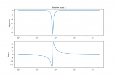
I did the measurement twice, once without any filters and once with -6dB of gain, and a Peaking filter of +6dB and Q=5.0 at 1 khz. Then I divided the two quite noisy measurements in REW to get the effect of the filter. The result is that I get a full agreement between theory and measurement:

In both curves, the peak is +6dB high and 160 Hz wide.
I would say whatever problem causes the discrepancy in your measurements have nothing to do with CamillaDSP.
About REW. My experience is that it's very solid. It's certainly easy to make nonsense measuerements with it, but when used properly the results are reliable.
Thanks to @seashell it's now easy to switch config at sample rate changes!
Take a look here: GitHub - scripple/alsa_cdsp: ALSA plugin for Camilla DSP
This is an Alsa plugin that acts as a playback device. It takes a template config file and updates the values for samplerate etc, and then launches an instance of CamillaDSP that it pipes the audio data to.
When for example samplerate is changed, it ends the stream to the CamillaDSP instance which then exits. Then it starts a new one with a new config.
It seems to work really well, even the picky PulseAudio is happy to use it via an alsa-sink.
You need to compile the plugin to install it, but the documentation in the repo is very good so this shouldn't be an issue. Note that in addition to gcc etc you also need to have "pkg-config" installed as this is needed to figure out where the plugin should be placed. Verify this with the command:
The output should be something like "/usr/lib64" or "/usr/lib/arm-linux-gnueabihf", not "command not found" or empty.
I am trying to wrap my head around alsa_cdsp and have a couple of questions.
1) How does a playback app trigger a rate change ? Does it need any foreknowledge of alsa_cdsp or need to pass it any parameters (other than writing PCM data to it) ?
2) How will it handle multiple sample rates if 2 apps play content simultaneously (e.g. playing music and the OS or desktop app plays an alert sound) ? Is it first come, first serve ?
Thanks much.
RustFFT 5.0 with avx has been released! It's used in the camillasp 0.5 betas and gives a nice 2x speedup of both the convolution and the synchronous resampler.Would this be of any value or is it too green ?
The rate is set when when the PCM is opened. No etra information is needed, it's enough to open the pcm at the rate you want.I am trying to wrap my head around alsa_cdsp and have a couple of questions.
1) How does a playback app trigger a rate change ? Does it need any foreknowledge of alsa_cdsp or need to pass it any parameters (other than writing PCM data to it) ?
2) How will it handle multiple sample rates if 2 apps play content simultaneously (e.g. playing music and the OS or desktop app plays an alert sound) ? Is it first come, first serve ?
Thanks much.
Alsa pcms don't handle multiple streams. If you try to open the same pcm twice the second attempt will fail with a device busy error.
If you need this, you will need a mixer device, or go via Pulseaudio.
Alsa Opensrc Org - Independent ALSA and linux audio support site
1/ I don't want a reference signal, I want to verify that the measurement can correctly measure a simple known filter (where a high-Q Peaking filter is the easiest choice).
2/ As things are now, I don't think this is working in your setup.
3/ At least not judging by the few plots you have shown. And before this is working there is really no point in trying to measure anything else.
3/ Obviously you can't measure the frequency response of the complete speaker that way, but that isn't what we are trying to do now.
3a/ We are still on the topic of verifying the measurement chain. You should place the mic as close as you dare to the driver that has your test
..Peaking filter in it's passband. And that driver should be something simple like a normal woofer or dome tweeter (not in a horn since).
Can you please show some results from the measurements on the different points in the chain?
I would say whatever problem causes the discrepancy in your measurements have nothing to do with CamillaDSP.
About REW. My experience is that it's very solid. It's certainly easy to make nonsense measurements with it, but when used properly the results are reliable.
Right.
This has been a most fascinating 48hrs.

I had to split up your points into numbers because it's the only way to make it clear.
You are partially right all along, but my speaker measurements were good.
In effect I had to end up working backwards.
This is really the only way to fight back assumptions & the elements which are counter intuitive.
Luckily I have 4 different linux systems, of which 3 have camillaDSP working et al, and ONE Win32 system, which doesn't run Camilla (and I don't want to try).
The win32 system has been used for calibration and measurement. I am happy with that.
It also has a decent audio editor.
The 2 sound cards work the same and perfectly.
I can only run Camilla on Linux, in this case x86 and Arm64.
They all work.
The studio sound card when in Linux has drivers for it for over a decade, and the onboard card (Intel AD1932?) turns out to be not so bad at all. (native kernel driver).
I have 3 different sound cards in fact, 2 of which are "onboard" and the other one a studio (PC) card which one would "assume" was tip-top, especially as they were very expensive (once)
I haven't really tested the hdmi headphone output on the ARM64, but I suspect it works ok.
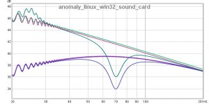
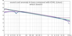
Here is the "give away" graph which was the EUREKA moment, so here we go:-
First we play the scan sys file through ICH6 and record it with VX, (it turns out to be fine), - NO DSP, - just direct and record with audacity. Table flat.
The we reverse it and play the same scan sys file thru VX and record with ICH6. NOT OK.
So here we have a sound card that records perfectly OK, but plays back with a huge roll off below 200hz, but ONLY on Linux.
The ICH6 is flat both recording and playback (but obviously noiser).
I tested with 2 different systems, BUSTER (Jan2021) and Ubuntu 18.04 (quite old).
Same result.
So here was my original question.
How come there is such a big difference between what we program into the .yml file on camilla, and what actually comes out of the speakers?
Here is the answer - about a -5dB anomaly only on Linux, and only in one frequency domain, with a variable response across the whole domain, because of the roll off.
It's one down to the "never assume anything" school!
I don't know why that is.
I can only assume it has something to do with a kernel latency issue or a driver bug, which doesn't exist on win32.
Luckily for me, ALL measurements I did on all speakers were done with win32 (cos I don't use camilla on that), so it turns out they were valid data.
The times we used Camilla, I could sense something was wrong, but couldn't put my finger on it.
How to do a work around for such a crazy situation..?
..well, no worries, really I am simply waiting for my dual sabre dac for the Raspberry pi, which will be here next week.
Hopefully the new HAT, will put us back in "precision" territory at last.
Thanks Hendryk.
Attachments
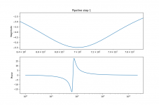
S1, Maybe I misinterpret the graphs, but i.m.o. the first step should be an unfiltered loopback measurement. That should provide a horizontal ruler flat measurement. maybe curving a bit @10Hz and 20kHz. In yours a see a 6db LP slope starting @dc instead of a flat horizontal line.
I just discovered this message that I had completely missed, sorry!Hello.
Henrik i created a new .tcz for my player with the camilladsp-0.5.0-Beta3.
It's working as expected, but i was wondering if it's possible to have the output ofshow the complete build release?Code:camilladsp --version
Not a problem, but i think it would be nice to have
Jesper.
This is very easy to do, I just have to add the beta suffix to the version number. And I agree this would be useful, will do it starting from the next version. I don't plan any more betas of 0.5.0, the next one will be the proper 0.5.0. After that I think Camilladsp is mature enough to make the jump to 1.0.0,
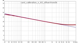
This looks much better, but that downwards slope of the curve looks odd. In this frequency range any semi-decent card should be completely flat, with no tilt.The we reverse it and play the same scan sys file thru VX and record with ICH6. NOT OK.
So here we have a sound card that records perfectly OK, but plays back with a huge roll off below 200hz, but ONLY on Linux.
But that brings a question mark. What is the "scan sys file"? Is it the REW test sweep recorded to wav, or something else? This info was maybe in one of the earlier posts, but didn't find it now
I have just had to accept it's what REW kicks out as a flat response graph for 0dB scan from 20hz-20khz, when you "import an audio file".that downwards slope of the curve looks odd
Steinberg produces this in a matter of seconds & when you look at it on their program it's perfectly flat.
If you look at this one,where I superimposed the response of the amp on it, there can be seen a clear divergence I measured at +4.5dB max starting at 5-6khz (measured on the DAW).
That I happen to know is specific to the amp and is highly unusual.
On REW it shows as the same amount, but the axis is literally tilted over (not that it really bothers me, at least you have a good idea where things are not flat, or diverge from flat).
TBQH I think REW is totally screwy, because on their last version there were explosions all over the frequency axis too, which made no sense whatsoever.
- Home
- Source & Line
- PC Based
- CamillaDSP - Cross-platform IIR and FIR engine for crossovers, room correction etc.