Happy New Year!
A little assistance if possible guys.
Building up a 2nd streamer that is very similar to my first build. I seem to have a problem with pSu rail sagging and getting hot.
For this build it is Pi less so is running Recieverpi alone into Fifo...etc.
I have left the ferrite bead in place on the Reciever and I'm trying to power Fifo dirty and also Recieverpi via gpio through Fifo dc input J3.
My psu for this rail goes 7v 25va trafo> 3A Bridge rectifier >XRK971 simple cap MX ..(a capacitance multiplier psu that is using LT1963 for 5v setting). Used before to good effect and mwasure 5v off load. Measure 10v dc into the psu off load. This drops to 8.8v loaded
Well when I power into the fifo dirty J3 the rail drips to 3v3. It is still enough to power the Fifo dirty an Reciever but it isn't right as the psu begins to heat up its pass transistor.
Tried different psu .....different topology and they dropped to 4.5v but still started to warm up.
I measured only 50ma draw.
Am I missing something?
Thanks in advance
Last edited:
So I have sussed out that my sagging rail is due to the ESS controller. I assumed it was my soldering somewhere and so I removed the extension kit but I still get the same problem mounting the controller directly to the fifo.
I guess the system won't function without the controller attached.?
I need to get into the fifo not locking problem too but probably need this working first
I guess the system won't function without the controller attached.?
I need to get into the fifo not locking problem too but probably need this working first
Help with FifoPi - LRCK signal not stable
I’m running RPi4 with Volumio and FifoPi Q3 (configured as Generic I2S driver in Volumio. When I check the output signal coming out of FifoPi (on J2, J7) MCLK out is ok but the LRCK signal shows “glitches” on a positive half wave. The frequency of the LRCK is ok but instead of staying high level for the half period of LRCK it drops low after each 8 MCLK clocks. “Low” period is ok - low all half period of LRCK.
I tried to play tracks with 16b / 44.1 kHz, 24b / 96 kHz, 24b / 192 kHz and the behavior is the same - LRCK goes low every 8 cycles of MCLK. All LEDs green on the FifoPi - PWR, I2S output, XO1 or XO2.
Anyone seen similar behavior of LRCK output? I tried also different driver in Volumio (Hifiberry DAC) and Moode Audio instead of Volumio but it is the same - drops of the LRCK signal every 8 cycles of MCLK.
I plan to use FifoPi with I2s to PCM board and dual AD1865 DAC but having the right signals out of FifoPi is the first step to fix.
Thanks
I'm afraid I cannot help with your problem above. I hope you sort it.
A little update....I have music playing.! Seemed to settle down and fifo locked on. Then I had no sounds but realised it was set to OSF bypass. Put that right and it is now playing.
One issue I would like some support with please. The ESS controller definitely has an issue. I unplugged the display from the extension cable and the regulator went right back to 5v and its pass transistor cooled down quickly. So there is definitely a problem on the controller display board.
Could I have some assistance debugging this please? I have visually checked the soldering and all seems good. No shirts on J3. Any tests I can perform.?
And it does llay music without the controller plugged in so that's a bonus for now.!
I am looking at building a UPNP streamer with FifoPi. The streamer will connect to a set of active speakers using SPDIF. I also would like to connect TV with Toslink to the streamer (using Receiverpi).
I now understand that FifoPi will introduce a delay to the audio signal causing sync issues between Video and audio on the TV. To prevent this delay is it possible to by pass FiFoPi for the ReceiverPi signal directly to the TransportPi?
Or is the audio delay by FifoPi very minimal and is the by pass not needed?
You will need to bypass the Fifo for TV. I have tried it.!
My controller issue seems to be down to the STM32 chip. It is getting really hot. I have tried to photograph the pins to see if any are bridged and one side does seem suspect. The soldering is much less clean than the other 3 sides. Way too small for me to re flow mind!
Photos shows one typical clean side and the one potential problem side.
Any thoughts?
Attachments
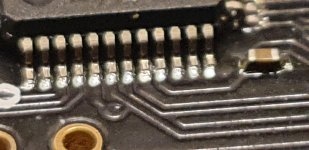
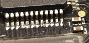
To my eye, 2 pairs at least of these pins are bridged.
You no doubt know this, but FWIW, if you have some solder wick and some rosin it is easy to remove. Just put some rosin on the wick and on the pins.. lay the wick across the length of the pin strip... and slowly drag a hot iron across the wick. The solder will melt and wick up to the copper. You will leave behind well soldered pins without the excess on all the pins you touch with the hot wick.
You no doubt know this, but FWIW, if you have some solder wick and some rosin it is easy to remove. Just put some rosin on the wick and on the pins.. lay the wick across the length of the pin strip... and slowly drag a hot iron across the wick. The solder will melt and wick up to the copper. You will leave behind well soldered pins without the excess on all the pins you touch with the hot wick.
Sorry, I can't recommend a temp as I only have the cheepie plug in 25w kind of iron. For smaller items like this I'd use a smaller tip and if you can't melt solder through the wick within a few seconds, turn up the heat and try again. I would avoid leaving an insufficiently heated iron in place for a long time as that will heat things up on the board. You want sufficient heat to quickly heat the wick to solder melting temp and get it out. The rosin just helps the solder soak into the wick and ensure good flow around the pin/pcb junction. There are lots of YouTube videos explaining surface mount soldering using an iron. Some suggest installing a part like this with too much solder and then wick it away. You end up with a really nice joint that is just the two surfaces with a little solder between them as opposed to big heaps of solder on each pin.
In case anyone else is using Pulsar OCXO clocks I thought I'd post this here to see if anyone can corroborate my findings. I am using a McFIFO with 2 x pulsar clocks (45/49) and have spent some time tweaking the power supply. I'd recently run out of tweaks to do(!) and realised that by setting HQPlayer to always oversample to 192k/32bits etc I could do without one of the clocks, so I pulled out the one that wasn't doing anything. I wasn't expecting the nice uptick I experienced. A little bit more musical, a few more noticeable acoustic cues, a little more depth in the soundstage, tighter base plucks.
I have a slightly strange and pimped setup where I use Ian's creations to re-clock the output from a pi3B+ and then feed that into a McFifo and re-clock it again. I played around with dual re-clocking a couple of years ago and the mod ended up staying. I tried removing the clock from the pi board but nothing very noticeable happened. Either being masked by the second re-clocking or perhaps the OCXOs react to power improvements more than the XO's I'm using in the Pi board.
Anyway, I've stopped tweaking and am enjoying the music.
Hope this is useful to someone,
Crom
One clock
Crom
I confirm a similar surprise. I currently run a single 45mHz clock. It's a WTMC. In testing with the old NDK clocks to confirm I could run with one clock, I too was surprised that pulling the 48mHz clock improved the sound.
I also set the player to resample everything with SOX vhq so I can listen to anything with one clock. In my case with an old TDA1541a DAC it sounds better at 44.1k than at 176k. Probably just just a DAC that's happier NOS.
- Home
- Source & Line
- PC Based
- IanCanada's Latest RPi GB Goodies Impressions... and your tweaks, mods and hints...