Ah. OK. Didn't realize you still live in the dark ages of manually toggling switches.
That's been another live on my side. Sorry for the ignorance.
I simply can't live with a DIY system based on "toggle-switches" (for every DC rail!)
or on-system control knobs anymore. No wonder you're leaving it on 24/7.
Enjoy.
Actually only two switches for many power supplies. Such engineering excellence... My music room also has many pot lights in the ceiling all turned all turned on at once with a single wall switch. Right out of the dark ages. It too is not dangerous, and I do not need a manual to turn the lights off.
Typo there, you meant 3a @ 5v
I leave mine on 24/7 too!
Good catch, thanks for the correction.
Do they really draw 3A sat doing nuffink?
No not at all, though what the actual draw is will depend on what is connected, if you were to have all kinds of USB devices drawing bus power that obviously increases the load considerably.
The RPi foundation has specified use of a 3 amp power supply with the 4B board to allow for some wiggle room. I have booted the 4B using a 2.5 amp supply no problem, even with a USB bus powered DAC connected, there is no lightning bolt icon indicating a voltage sag due to excessive current draw.
If you were going to see that problem it would be during the initial boot sequence, when the most juice is required, or when too many power hungry devices are attached.
using a different DAC
I'm trying use a Aroiodac with the ReceiverPi in a RPI free mode, but ihave no audio out.
Is this combination possible? I suspect that the Aroiodac is a master DAC.
I'm trying use a Aroiodac with the ReceiverPi in a RPI free mode, but ihave no audio out.
Is this combination possible? I suspect that the Aroiodac is a master DAC.
Not if there is only a market for 10/30 boards with all the R+D time for Ian.
I would guess at a weeks work to design/prototype/populate/test/troubleshoot,
REV 1.1 repopulate test. At what $ 30/Hour + parts.
I would guess at least $ 200 more, if 20 people were still interested at that price.
Some will probably wish for dual DAC chips making the market smaller still.
I would be interested in the 200-300 USD range for a 2x single-chip AK4499 DAC boards and I have a few friends that would be too
")
I hope it is financially viable for Ian to do a design.
I have seen that Dac.
I am not sure a dual-mono build is required for the 4499, but a pretty good value board all the less
I'd be happy either for a single or dual-mono board from Ian.
Added an Allo Shanti LPSU and swapped out the Rasp.Pi4 for an Allo USBridge Sig to my FIFO and DAC stack.
Cleans up the Pi noise nicely.
Allo claim 0.08 uV noise from the LPSU , 2x 3F supercaps on the output.
Thanks for the feedback. Validates what I have been hearing too.
Edit: I think the best result I have had so far with the USBsig is using a USB to I2s board.
DC on the output
Hi all.
You may or may not recall I was building another DAC for my brother to go in his fairly costly (commercial) system. He has a high end vinyl front end and he fancied a streamer to save his cartridge.
Well it has been in place for a couple of weeks now and he is very pleased.
I am on house sitting duty as he is away for this evening so I tried the system just now. Sounding good...crank the volume a bit.....the dac is set to full level 0db so I am using the remote for his amp (relay volume control).
As the levels get higher I notice some clicks when the volume relays switch....hhhmmm....I have heard this before when I got my Salas DCG3 wrong......well soon enough I have this expensive amp shutting down. Fortunately it has DC speaker protection built in!
So long story short...how do I test for DC out of the XLRs? And what would be the first culprit?
This is running one of the giveaway untested IV std stages Ian kindly gave away. It was indeed problematic on delivery and I had the fortune of receiving the kind help of Simon sq225917 to sort it.
Any advice much appreciated.
Thanks
Attachments
ES9028Q2M without ESScontroller
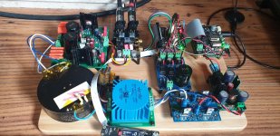
I’d like to test following Ian’s equipment together. Should it work?
I’d like to test following Ian’s equipment together. Should it work?
- Odroid C1+ as a source with IsolatorPi and DOP Decoder v1
- u.fl connections from IsolatorPi to McFifo/McDualXO
- u.fl connections from McDualXO to ES9028Q2MDacHAT using RpiI2SAdapter (mounted on topp of DAC)
Jimk04
Why do you use 20cm of Ribbon cable? Why don*t you stack dac on the top of a Fifopi?
Output stage is not so problematic and can be on side.
For dc measure in mV voltage from gnd to POS and NEG pin. It depends of opamps. More than few mv will for sure cause clicks on power amp at high volume.
Why do you use 20cm of Ribbon cable? Why don*t you stack dac on the top of a Fifopi?
Output stage is not so problematic and can be on side.
For dc measure in mV voltage from gnd to POS and NEG pin. It depends of opamps. More than few mv will for sure cause clicks on power amp at high volume.
Hi Androa.
I had read of some trying the dac away from the rest of the stack to minimise noise/RFI from the Pi? And it also 'flattens the build to allow lower chassis. I may well try it back on top of Fifo as I think this build will end up Pi less.
So I'm looking into the +/- psu and opamps for the DC issue.?
Thanks for your help
Ian,
Have you had a chance to experiment with the Newclassd Neutron Star 2 clock? I see that JackLee has found that two of these clocks installed with FifoPi interfere with each other.
I am quite interested in using the NS2 clocks. I can certainly hear a difference from NDK to Crystek to Accusilicon and would like to try the NS2.
Thanks.
I have seen that Dac.
I am not sure a dual-mono build is required for the 4499, but a pretty good value board all the less
I'd be happy either for a single or dual-mono board from Ian.
I'd also be interested. I haven't done much digging around the different versions of this chip (so I may be arguing a moot point) but I'd be even more interested if Ian selected the non-mobile version of the chip.
Last edited:
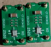
NDK2520XOadapterKIT with NZ2520SDA
I today tried to solder clocks on NDK2520XOadapterKIT. Ordered NDK NZ2520SDA 24.576MHz & 22.5792Mhz from DIYINHK.
First I tried with hot air gun from the other side of adapter, but this didn't work, as probably the pcb is too thick and I didn't want to apply too much heat.
I then tried heating the four pads one by one, using solder paste. It worked well.
Unfortunately I could'nt get eiter of them working when installed on FifoPi.
Might it be that I damaged the clocks with soldering iron (too much heat)? I have soldered NDK clocks before with same technique.
Would really appreciate hints, how you have managed to solder them on the new adapters. Here's a photo also.
Attachments
- Home
- Source & Line
- PC Based
- IanCanada's Latest RPi GB Goodies Impressions... and your tweaks, mods and hints...