How did you see a 100MHz clock looks like a sin wave?
There are lots of ES9038Q2M dacs that come with 100Mhz clocks. in some cases we have experimented with replacing the original clocks with Crystek 575 100MHz clocks. For one example: ES9038 Q2M I2S DSD Optical Coaxial Input Decoder DAC Assembled Board DC9-15V 8751762607403 | eBay
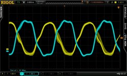
Of course with a 100MHz scope, a 100MHz clock will look like a sine wave anyway, or pretty close to that. The first harmonic frequency of a 100MHz square wave is at 300MHz, well above the maximum frequency of a 100MHz scope. However, even using a 600MHz scope, Crystek 575 waveforms don't look very square. The blue trace below is the output of a 100MHz Crystek 575 100MHz clock, and the yellow waveform is the MCLK signal from a Sabre dac exported on a GPIO pin. The Crystek clock looks better than some cheaper competitors, but still not all that square. The dac GPIO MCLK output looks pretty much like a sine wav. Of course, its possible if using active differential probes it would be possible to see somewhat better looking waveforms, but not in all cases. Some ultra-low jitter clock manufacturers include output waveforms in data sheets, and they rarely look all that square at very high frequencies. It probably would make more sense to have LVDS clocks and dacs if we ever get to DSD2048. Even DSD1024 is really pushing it with data being clocking on both clock edges, IMHO.
Attachments
Last edited:
Both scope and probe are rated at 600MHz bandwidth.
Risetime of Crystek 575 is rated at 2ns max 20%-80% Vdd.
A 100HMz clock has a period of 10ns, which is to say a half-cycle is 5ns. With a 2ns risetime, there might actually be 3ns when it is at or above 80%Vdd (or at or below 20%), and of course we expect some loss of detail on that with only a 600MHz scope and 600MHz probe combination. Better to have a 5GHz scope, or faster.
In the above regard Crystek clocks are pretty good.
NDK NZ2520SD which are available up 80Mhz are rated for a rise time of 6ns max.
Hopefully we will always be fortunate, and have much less than max risetimes")
What concerns me about reclocking as it is normally done, is that clocks are delayed maybe by NB3L553 with as much as 35ps output skew (typical), with the skew possibly the main timing complication/uncertainty if one output drives the dac MCLK, and another output drives the reclocker flip flop. Then there are further delays (and sometimes unknown capacitive loading) by cable and PCB traces, and signals are typically delayed by something like Potato PO74G74A which is maybe 2ns if not loaded with a lot of capacitance, but unbuffered they are not really 50-ohm transmission like drivers. In terms of maxmum frequency Potato parts are sensitive to capacitive loading.
Making sure the whole thing really works as intended could get rather complicated. Perhaps more so when there are multiple boards and interconnects involved. Just one loose or otherwise imperfect RF connection could cause unintended and or erratic operation.
Risetime of Crystek 575 is rated at 2ns max 20%-80% Vdd.
A 100HMz clock has a period of 10ns, which is to say a half-cycle is 5ns. With a 2ns risetime, there might actually be 3ns when it is at or above 80%Vdd (or at or below 20%), and of course we expect some loss of detail on that with only a 600MHz scope and 600MHz probe combination. Better to have a 5GHz scope, or faster.
In the above regard Crystek clocks are pretty good.
NDK NZ2520SD which are available up 80Mhz are rated for a rise time of 6ns max.
Hopefully we will always be fortunate, and have much less than max risetimes
What concerns me about reclocking as it is normally done, is that clocks are delayed maybe by NB3L553 with as much as 35ps output skew (typical), with the skew possibly the main timing complication/uncertainty if one output drives the dac MCLK, and another output drives the reclocker flip flop. Then there are further delays (and sometimes unknown capacitive loading) by cable and PCB traces, and signals are typically delayed by something like Potato PO74G74A which is maybe 2ns if not loaded with a lot of capacitance, but unbuffered they are not really 50-ohm transmission like drivers. In terms of maxmum frequency Potato parts are sensitive to capacitive loading.
Making sure the whole thing really works as intended could get rather complicated. Perhaps more so when there are multiple boards and interconnects involved. Just one loose or otherwise imperfect RF connection could cause unintended and or erratic operation.
Last edited:
Nyquist Sampling Theorem and Stupid Question
IMHO, I think 100MHZ scope can not detect 100MHZ square wave and sine wave based on nyquist sampling theorem and my experience on my 20MHZ analog scope and 500MHZ digital scope.
Could you please let me know how to detect 100MHZ signal using 100MHZ scope ?
Please overlook my stupid question, I have no theoretical background about electronics.
Of course with a 100MHz scope, a 100MHz clock will look like a sine wave anyway, or pretty close to that.
IMHO, I think 100MHZ scope can not detect 100MHZ square wave and sine wave based on nyquist sampling theorem and my experience on my 20MHZ analog scope and 500MHZ digital scope.
Could you please let me know how to detect 100MHZ signal using 100MHZ scope ?
Please overlook my stupid question, I have no theoretical background about electronics.
What concerns me about reclocking as it is normally done, is that clocks are delayed maybe by NB3L553 with as much as 35ps output skew (typical)
Sorry. Not sure what I was thinking when I wrote the above. 35ps is too little for most of what I was talking about. There is another dac project I have where I see sound quality sensitivity related to I2S timing on the scale of 100ps or less, but not an issue for what I was attempting to address earlier today.
Again, sorry if any confusion.
It depends. If computer software does any resampling for any reason, and sometimes operating systems such as Windows will do it without telling you, and or if resampling occurs in a player such as HQplayer, that processing can and will change the bits and potentially make quite a large difference in sound quality. At other times it can sound slightly bad somehow, but it may be less obvious that the bits have been changed.
Then there are the mechanisms that Greg mentioned. There is ground common mode noise that can turn into a ground currernt. There is HF and RF noise from various sources in a computer that can couple into signal and ground connections, etc. And, of course there is what ESS refers to as 'transport jitter.'
Some people have believed that galvanic isolation and 'reclocking' could eliminate all such issues, but as you have already heard, it is really an issue of attenuation of noise that occurs. How much attenuation is necessary? Basically, until you can't hear any of effects of it, and can't measure much or any of it remaining.
Optical isolation is good because it eliminates current flowing between devices, especially if the optical cable is long enough to keep sending and receiving devices far enough apart such that electromagnetic coupling between devices is also strongly attenuated.
However, optical interfaces increase jitter. If there is too much jitter, ASRC may be needed to recover the signal before it can even be run through a separate 'reclocker.'
I would also point out that most reclocker circuits are not designed to work well at very high data rates. That's because propagation delay effects between clocks, dacs, and I2S signals are not usually accounted for to close tolerances. Delays through chips such as clock buffers, D-flip flops, etc., and delays of cable lengths, etc., typically work out well enough time aligned at low to moderate data rates, but can be fairly skewed relative to the timing constraints of high sample rate data and clock frequencies.
In addition, audio clocked around 50MHz or 100Mhz using LVCMOS devices starts to look a lot more like sin waves than square digital pulses. That makes data setup and hold timing constraints very hard to assure, say, as data is clocked into a dac chip. It can also make it complicated to know if reclocking is really working as intended.
Hi Markw4,
Your 100MHz clock waveform doesn’t look that correct. I cannot see a clear rising edge or falling edge, as well as ringing, overshoot and reflections. Looks like the bandwidth is not sufficient though you said you oscilloscope has 600MHz bandwidth. Just hope you can figure out what’s the problem of the measurement.
The attached picture is the waveform of a typical 98.3040MHz audio clock I measured while back. There are roughly 1ns rising and falling time, as well as ringing and everything. It doesn’t look like a sin wave. My oscilloscope has 1GHz bandwidth with sampling rate up to 8GS/s. It doesn’t superior too much than yours.
If you cannot see the true waveform, what you get from your measurement will mislead your analyzing result. For example, when you talking about the 100MHz clock, you are worry about the setup time and hold time because of that waveform you saw. Actually Tsu and Th have nothing to do with the accuracy and sound quality. It’s all about the tolerance of your digital system. For a synchronized logic system, they describe the relationship between the original clock and date (or generated clock). If the Tsu or Th condition (depend on the logic chips) doesn’t meet, the output will be wrong, and you will hear noise or get malfunction (So you will clearly know something wrong). If that is the case, it will be totally unacceptable for audio application. Otherwise, the digital music will be 100% correct. It’s black and white and nothing in between.
In the digital domain, the only thing impacts the sound quality is the jitter of the MCLK. Propagation delay and skew are all totally different concept to the jitter. They will have no any business with sound quality as long as all timing requirements are met.
Clock frequency doesn’t have direct relationship with the clock quality. Both 100MHz and 50MHz clock can have same raising and falling time, same overshoot, same reflection. The difference could be only the plateau time. Actually, if they have same phase noise numbers, the higher frequency ones will have less jitter.
So, higher frequency clock closing to 100MHz doesn’t look like a sin wave and it doesn’t degrade the sound quality (may upgrade) under the same condition (as long as your DAC can work with).

CLOCK98.3040MHz by Ian, on Flickr
Good weekend,
Ian
Hi,
I want to connect two battery boards to the dac. Using the 13v rails of the 2 boards in parallel to lower ps impedance to the iv stage. In the manual there is only mention of putting the batteries in series, not in parallel.
Is there a downside of using them in parallel?
I also have a 7,7A 19v switching ps, will this suffice for feeding two boards in parallel? The manual states a minimum of 3,5A but the charge current on the display is around 6A max (is this the current at 3,3V?)
Both scope and probe are rated at 600MHz bandwidth.
Risetime of Crystek 575 is rated at 2ns max 20%-80% Vdd.
A 100HMz clock has a period of 10ns, which is to say a half-cycle is 5ns. With a 2ns risetime, there might actually be 3ns when it is at or above 80%Vdd (or at or below 20%), and of course we expect some loss of detail on that with only a 600MHz scope and 600MHz probe combination. Better to have a 5GHz scope, or faster.
In the above regard Crystek clocks are pretty good.
NDK NZ2520SD which are available up 80Mhz are rated for a rise time of 6ns max.
Hopefully we will always be fortunate, and have much less than max risetimes
What concerns me about reclocking as it is normally done, is that clocks are delayed maybe by NB3L553 with as much as 35ps output skew (typical), with the skew possibly the main timing complication/uncertainty if one output drives the dac MCLK, and another output drives the reclocker flip flop. Then there are further delays (and sometimes unknown capacitive loading) by cable and PCB traces, and signals are typically delayed by something like Potato PO74G74A which is maybe 2ns if not loaded with a lot of capacitance, but unbuffered they are not really 50-ohm transmission like drivers. In terms of maxmum frequency Potato parts are sensitive to capacitive loading.
Making sure the whole thing really works as intended could get rather complicated. Perhaps more so when there are multiple boards and interconnects involved. Just one loose or otherwise imperfect RF connection could cause unintended and or erratic operation.
Hi Ian,
Thank you for posting that scope picture. Its enough to make me want to go back and double check the some things.
Hi Markw4,
That sounds great. Please let me know if you have new update.
Regarding the NB3L553, I’d like to discuss a little bit more about this topic. Just want to clarify some concepts. Hope it can be some helps to the community members to understand more about signal integrity and high speed logic design. Please correct me if I’m wrong.
The first concept I want to discuss is the propagation delay. Propagation delay is the time shift delay between the output and the input signal of a buffer. It has relationship with voltage, temperature and silicon itself. For a given buffer under the given condition, that delay time will keep constant without changing for each channel. If the signal is the MCLK, the propagation delay can add a couple of ns delay to it. However for a DAC, it doesn’t make any difference with and without that amount of delay. If the signal is data or generate clock (such as SCK), the propagation delay will increase a couple of ns to the setup time (which might be even better for tolerance). As long as all timing requirements are met, the digital music will be 100% correct and will have no impact to the sound quality. In the real world, there is no butter without delay. NB3L553 has propagation delay between 2ns to 4ns which is pretty reasonable. If you heard something called "zero delay buffer", then just simply don't touch it. The zero delay buffer is just a PLL. It can generate a great deal of jitter which would degrade a lot to the clock quality.
The next, let's talk about skew. Skew is the time difference of propagation delay between channels.
Why there is skew? Because in the real world, no channel can be made identical to each other. Skew will also keep constant without changing under the same condition. Does skew impacts sound quality? The answer is NO. As clock signals, skew shift the propagation delay a little bit between channels. For data signal or generated clock signals, it change a little bit to the tolerance of setup time and hold time. As long as all timing requirements are met, in either case, it doesn't change the sound quality. NB3L553 has around 35ps skew between channels, which is also a very reasonable number.
So, which specification has business with sound quality for a clock buffer? Yes, It is the additive jitter. Additive jitter is the amount of jitter added to the output signal after a buffer by comparing with the input signal. It can degrade the clock quality after going through the buffer. However, for NB3L553, the additive jitter is only rated at around 18fs. That amount of additive jitter increases the phase noise by less than 3dB over -110 to -160dB phase noise floor. This amount of additive jitter can be ignored for most of the digital audio applications. NB3L553 is the best one among all clock buffers. Please refer to the attached NB3L553 phase noise plot for more details.
Seven years ago, I'm the first one who started using NB3L553 for FIFO and other digital audio applications. After that time, many followers took the same component by referencing my design. I think the reason is very clear.
So again, as long as all timing requirement are met (it needs to be carefully designed and scheduled inside FPGA logic, that was my job
), there is no need to worry about the propagation delay and skew. To achieve better sound quality, we only need to focus on selecting the better clock and the right clock buffer.
NB3L553AdditiveJitter by Ian, on Flickr
Regards,
Ian
Last edited:
That sounds great. Please let me know if you have new update.
Hi Ian,
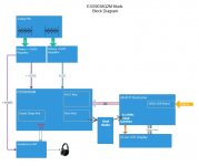
There is only one thing bothering me that I am probably not equipped to adequately measure. Using LMK01000 I divided my own ES9038Q2M dac 100MHz clock by 4 to get 22.5MHz to synchronously clock the output of an AK4137 doing upsampling and DSD conversion. The AK4137 generates 12.5MHz DSD256 clock and data signals that are fed back into the dac I2S inputs. The dac runs fine without dropouts or other indication of I2S problems except for one peculiar effect. LMK01000 delay divider delay can be adjusted in 150ps steps, and I find that best sound quality out of the Sabre dac (running in async mode @100MHz, DPLL bandwidth =1) is very sensitive to LMK01000 clock delay. The best sound is with a particular LMK01000 150ps delay step used to drive AK4137 output. I have checked to see what exact timing ES9038Q2M wants by putting it in master mode so it generates the DSD clock. The AK4137 clock delay that makes ES9038Q2M sound best may be slightly off from that 150ps (or so) window of best sound quality, hard to say exactly. To resolve 150ps timing changes accurately I would probably need a better scope and probably a couple of active differential scope probes, so it would seem. What exactly is causing the sound quality improvement in such a small time window may have to remain a mystery for now since my scope does not show a clear anomaly of any waveform. However, since I think you have a better scope than me, maybe you would like to give it a try sometime and see what you think. Just requires putting a u.fl connector where the AK4137 22.5MHz audio clock is on the AK4137 board, and sending it divided MCLK from the dac. The nice thing about it is the sound quality at its best can be pretty close to what HQplayer software can do. However, HQplayer requires a powerful i7 computer, and costs $150-$250. By comparison, AK4137 could be much cheaper and have lower latency. So, it is a worthwhile thing if sound quality can be optimized. One thing that might be an easy solution would be to clock both the dac and and AK4137 synchronously at 22.5MHz, in which case any timing quirks should be much easier to sort out. Eventually, I will probably try that if nobody else wants to. Its just going to have to be delayed by other things taking higher priority for awhile. If it weren't for measurement problems when I was trying to sort out the 150ps mystery with the best scope I had, I wouldn't have started worrying about possible similar problems occurring as audio sample rates continue to rise with each advance in technology.
-Mark
EDIT: Also, just to be clear, the 100MHz clock I was using on my dac does not use any of the clock or FIFO boards you make. It was a separate project that is working fine, but set aside for now. I started building one of your dacs in an effort to more quickly get another test dac working. So, any problems I have had with clock waveforms captures were taken with other dac hardware and with the clock signals in a very inconvenient place for good scope probing practices. There is a good chance if I took that dac apart and put clock u.fl clock test point connectors on it for scope measurements that my waveform captures would look much better. That seems likely, in fact.
The only reason that caused me to abandon use of your dac design was the lack of full stereo AVCC connections.The AVCC won't work for my purposes, so I am off and working on yet another dac for now.
Attachments
Last edited:
Hi Ian,
One more thing about clock waveforms: As I was saying at one point before, not all clocks actually do put out square waves. Some clock manufacturers claim they can make lower jitter sine wav clocks than square wave clocks. Maybe I am not the only person to have noticed some sine or near sine wave clocks in use. In fact, looks like some people have taken to squaring them up with some extra logic chips: https://www.diyaudio.com/forums/digital-line-level/273474-dac-dac-223.html#post5828044 ...Although, Terry may be referring to use with discrete clock oscillator circuits, not sure. Knowing him, could be. The usual method clock manufacturers say they use for converting low jitter sine wave clocks to square wave clocks is to clip off the sine wave peaks.
Regards,
Mark
Last edited:
Hi Ian,
One more thing about clock waveforms: As I was saying at one point before, not all clocks actually do put out square waves. Some clock manufacturers claim they can make lower jitter sine wav clocks than square wave clocks. Maybe I am not the only person to have noticed some sine or near sine wave clocks in use. In fact, looks like some people have taken to squaring them up with some extra logic chips: https://www.diyaudio.com/forums/digital-line-level/273474-dac-dac-223.html#post5828044 ...Although, Terry may be referring to use with discrete clock oscillator circuits, not sure. Knowing him, could be. The usual method clock manufacturers say they use for converting low jitter sine wave clocks to square wave clocks is to clip off the sine wave peaks.
Regards,
Mark
Hi Mark,
XOs with LVTTL, LVCMOS or any kind of logic levels are all in square wave output. That's for sure. Crystal oscillators normally has sin wave internally. But need to be converted into square wave to have those logic output. That's what the circuit board of CCHD957 did .
Ian
Last edited:
Hi Ian,
There is only one thing bothering me that I am probably not equipped to adequately measure. Using LMK01000 I divided my own ES9038Q2M dac 100MHz clock by 4 to get 22.5MHz to synchronously clock the output of an AK4137 doing upsampling and DSD conversion. The AK4137 generates 12.5MHz DSD256 clock and data signals that are fed back into the dac I2S inputs. The dac runs fine without dropouts or other indication of I2S problems except for one peculiar effect. LMK01000 delay divider delay can be adjusted in 150ps steps, and I find that best sound quality out of the Sabre dac (running in async mode @100MHz, DPLL bandwidth =1) is very sensitive to LMK01000 clock delay. The best sound is with a particular LMK01000 150ps delay step used to drive AK4137 output. I have checked to see what exact timing ES9038Q2M wants by putting it in master mode so it generates the DSD clock. The AK4137 clock delay that makes ES9038Q2M sound best may be slightly off from that 150ps (or so) window of best sound quality, hard to say exactly. To resolve 150ps timing changes accurately I would probably need a better scope and probably a couple of active differential scope probes, so it would seem. What exactly is causing the sound quality improvement in such a small time window may have to remain a mystery for now since my scope does not show a clear anomaly of any waveform. However, since I think you have a better scope than me, maybe you would like to give it a try sometime and see what you think. Just requires putting a u.fl connector where the AK4137 22.5MHz audio clock is on the AK4137 board, and sending it divided MCLK from the dac. The nice thing about it is the sound quality at its best can be pretty close to what HQplayer software can do. However, HQplayer requires a powerful i7 computer, and costs $150-$250. By comparison, AK4137 could be much cheaper and have lower latency. So, it is a worthwhile thing if sound quality can be optimized. One thing that might be an easy solution would be to clock both the dac and and AK4137 synchronously at 22.5MHz, in which case any timing quirks should be much easier to sort out. Eventually, I will probably try that if nobody else wants to. Its just going to have to be delayed by other things taking higher priority for awhile. If it weren't for measurement problems when I was trying to sort out the 150ps mystery with the best scope I had, I wouldn't have started worrying about possible similar problems occurring as audio sample rates continue to rise with each advance in technology.
-Mark
EDIT: Also, just to be clear, the 100MHz clock I was using on my dac does not use any of the clock or FIFO boards you make. It was a separate project that is working fine, but set aside for now. I started building one of your dacs in an effort to more quickly get another test dac working. So, any problems I have had with clock waveforms captures were taken with other dac hardware and with the clock signals in a very inconvenient place for good scope probing practices. There is a good chance if I took that dac apart and put clock u.fl clock test point connectors on it for scope measurements that my waveform captures would look much better. That seems likely, in fact.
The only reason that caused me to abandon use of your dac design was the lack of full stereo AVCC connections.The AVCC won't work for my purposes, so I am off and working on yet another dac for now.
@Markw4
In you block diagram, ES9038Q2M will be synchronized with AK4317 outut. However AK4317 is still working in ASRC mode. So the over all system is still in ASRC not SYNC.
How did you generate the 25MHz clock from 100MHz? Do you have schematic?
Regards,
Ian
IanSeven years ago, I'm the first one who started using NB3L553 for FIFO and other digital audio applications. After that time, many followers took the same component by referencing my design. I think the reason is very clear.
So again, as long as all timing requirement are met (it needs to be carefully designed and scheduled inside FPGA logic, that was my job
NB3L553AdditiveJitter by Ian, on Flickr
Regards,
Ian
Thank you for this excellent explanation.
I think your chart makes it clear, the relative importance of the clock phase noise in determining sound quality (given reasonable care is taken with ufl connectors and cable length etc.).
Hi Ian,
One more thing about clock waveforms: As I was saying at one point before, not all clocks actually do put out square waves. Some clock manufacturers claim they can make lower jitter sine wav clocks than square wave clocks. Maybe I am not the only person to have noticed some sine or near sine wave clocks in use. In fact, looks like some people have taken to squaring them up with some extra logic chips: https://www.diyaudio.com/forums/digital-line-level/273474-dac-dac-223.html#post5828044 ...Although, Terry may be referring to use with discrete clock oscillator circuits, not sure. Knowing him, could be. The usual method clock manufacturers say they use for converting low jitter sine wave clocks to square wave clocks is to clip off the sine wave peaks.
Regards,
Mark
Hi Mark,
I used a Tiny Logic (NC7SZ04) inverter to square up a batch of sine wave OP
of OCXO's I had procured. The inverter also had schmitt trigger IP which is
good for squaring the slower edge of sine wave.
I made the decision based on data here Ref P18 / Table 3-1
http://www.ham-radio.com/sbms/LPRO-101.pdf
74AC04 was the best and Tiny Logic looked slightly better again.
cheers
Terry
@Markw4
In you block diagram, ES9038Q2M will be synchronized with AK4317 outut. However AK4317 is still working in ASRC mode. So the over all system is still in ASRC not SYNC.
How did you generate the 25MHz clock from 100MHz? Do you have schematic?
Regards,
Ian
I think a good option for this is a simple dual flip flop divide by 4 circuit.
T
@Markw4
In you block diagram, ES9038Q2M will be synchronized with AK4317 outut. However AK4317 is still working in ASRC mode. So the over all system is still in ASRC not SYNC.
Yes, that is correct. It is similar to how Benchmark DAC-3 works. It also allows for possible compatibility with SPDIF.
How did you generate the 25MHz clock from 100MHz? Do you have schematic?
For experimental purposes, I used LMK01000.
http://www.ti.com.cn/cn/lit/ug/snau037a/snau037a.pdf
http://www.ti.com/lit/ds/symlink/lmk01000.pdf
Regards,
Mark
Last edited:
I think a good option for this is a simple dual flip flop divide by 4 circuit.
That may be. Or, it might suffice to clock both dac chip and AK4137 at 22.5MHz, or maybe at 24MHz.
Clearly, I was not able to try every possible combination that might work.
My intent by leaving the dac chip at 100MHz was so that it could still play all possible Sabre supported sample rates if the owner desired.
Yes, that is correct. It is similar to how Benchmark DAC-3 works. It also allows for possible compatibility with SPDIF.
For experimental purposes, I used LMK01000.
http://www.ti.com.cn/cn/lit/ug/snau037a/snau037a.pdf
http://www.ti.com/lit/ds/symlink/lmk01000.pdf
Regards,
Mark
@Mark
I saw three problems in you solution if you use LMK01000, but I could be wrong.
1. Your system will have three clock domains. One is the ES9038Q2M, The other is the AK4137, and the third is the xMOS USB. All of the three domains are not synchronized to each other.
2. In your system, there will be two ASRCs. One is the AK4137 and the other is the ES9038Q2M.
3. LMK01000 is a PLL itself. The PLL jitter will be applied to ES9038Q2M input. Though it was designed as audio PLL, but I don't think it qualified to audiophile level. Could only be good enough for home theater system.
I'm not sure if it can achieve the good sound quality as you think. But at least it can not keep everything original and native.
If AK4137 can take up to 25MHz clock, I would suggest using flip-flops to generate 25MHz clock from the 100MHz.
Regards,
Ian
Last edited:
- Home
- Source & Line
- PC Based
- IanCanada's Latest RPi GB Goodies Impressions... and your tweaks, mods and hints...