Mark, I knew that when I exchanged a post with Supersurfer that we would get another comment about idiots who spend enormous sums of money with so little results in your opinion. OK WE GET IT. But it is still a bit off putting.I keep trying to explain that power supplies, caps, and clocks can only do so much. Some people here are spending a lot on exotic parts for what in the end can only be mediocre sound quality, IMHO,
But I do appreciate you stating your goals centered on DSD512 from an ESS based DAC. Knowing that is your path puts lots of your posts in context, so thanks for that clarification. I have no doubt that if I could obtain DSD master tapes without audio engineering, I could enjoy a level of sound quality unobtainable given my self imposed limitations. But I like to get great sound from redbook using DIY gear without spending a lot. I have a lot of redbook material, and refuse to spend money on DSD. I am actually having fun getting sound that satisfies me from a 30 year old DAC chip and even older tubes and drivers. My criteria for sound is basically natural with a lot of low level detail. While I appreciate your position that exotic filters on an ESS dac is the road to perfection, somehow filters always leave me wanting for a sense of reality that is inversely proportional to the amount of filtering. I realize that is a different perception, but it is what I perceive. I think there is no right or wrong in audio appreciation and different people perceive the same thing differently. But to assume that people other than yourself only experience mediocre sound quality is a stretch.
So where have I spent all this money that is so concerning?
Not on transformers or chokes. I use a lot of them but source them from an electronics junk yard. I see you use shiny new R-core. What did that cost? Not on exotic tubes or capacitors. I use Russian military surplus. Certainly not buy linear power supplies. These are all wired point to point for pennies on the $. Maybe its the Blackgate caps. I bought these from Partsconnextion when they were cheap and I drove to their pickup counter to avoid shipping. Perhaps it is the double crown 1541a chip. Yes that was indulgent at $100. BTW, I could sell the Blackgates or the 1541a for many times what I purchased it for after enjoying them for years. Can you say the same for your Benchmark DAC or all the various ESS systems you have built? I use supercaps which came at no cost to me from my former business.
Ah! It must be the clock!! Yes, I fully grasp that there may be a limit to what a clock can deliver. The upgrade to NDK SDA (which were a gift gratefully received from another member) was substantial and brings me much audio joy. The Laptech crystals that Andrea is having custom made have pretty amazing specs. I realize however that the NDK might be the point of diminishing return in this setup. But, like my TDA1541a and the Blackgates, these Laptech crystals will IMHO be unobtainable in the future, and their exceptional spec if not rewarding for this DAC might one day be valued and useful in some other project. If they were provided as an option to some audiophool commercial DAC they would cost thousands. So for $100 I'll have a great time and enjoy them for years. And if there is a limit to what a clock can do, I look forward to discovering that myself. It is DIY after all. I'll happily report if that is the case and someone else can use that info for their own calculus.
I have a lot of redbook material, and refuse to spend money on DSD.
Me too. I guess I wasn't clear, sorry.
The terminology, 'upsample and convert to DSD' means that PCM including redbook CD is converted to DSD512 just for playback as though the dac were designed to work that way to begin with. It's just another way to use sigma-delta modulation to reproduce music, including redbook PCM. The reason the upsampling and DSD conversion is done in an i7 computer rather than inside the dac chip is because the DSP calculations require too much computing power to put inside a dac chip.
By the way, the JLsounds USB board I am using comes pre-equipped with NDK SDA clocks, and galvanic isolation. It costs $85US. It can also use external clocks if desired.
Last edited:
So where have I spent all this money that is so concerning?
Sorry, ran out of editing time on the last post.
Didn't mean to single you out, if I inadvertently did. Unfortunately, there are some costs to making a good dac. I had hoped to find otherwise, but that seems to be the reality at the moment.
What I don't understand or agree with is what appears to be a tendency to focus modification and upgrade efforts in certain areas that sorta-defacto group leaders are comfortable with, but with some lack of focus in other problem areas. Again, the reality with dacs today is that all problem areas that can be fixed need to be fixed, if the goal is to achieve best sound quality.
Last edited:
Hey Mark, no problem. Guess I needed to vent. All good.
The JLsounds USB board does appear to offer a good value prop. If I recall, does it not also have built in I2StoPCM conversion or should I say synchronous PCM? That is one feature that would have been excellent if Ian had chosen to put that into FIFOPi. It would eliminate the I2StoPCM board and another round of processing. Small market I guess, so hard to justify.
My DAC heros were Thorsten Loesch, ECdesigns, and Lukasz Fikus. But I think we have pretty much beaten the old Philips chip as far as it can go so your work on ESS is well placed. For me, I'd like to see someone run with Fikus innovation of using tubes to strip the DSD signal off the carrier and combine that with a FIFOPi that can mute the output between tracks. I believe there is some purity to be found there. But I am off topic.
if the goal is to achieve best sound quality.
Though 'best sound quality' means different things to different people.
Once you reach a certain level it becomes 'preferred sound quality'.
Last edited:
Into the weeds with PS
Speaking of going into the weeds with power supplies, one other experiment that intrigues me is to replace the silicone rectifier on the clock PS with a tube rectifier. There was such an obvious improvement going to super soft recovery diodes perhaps there's still more juice to be squeezed. Someone else was scoffing the notion of good clocks quipped that unless we went with tubes, the diodes will completely pollute the clock supply negating their spec. Ok, I'll try tube. Yeah I know just buy a battery, but that would be too easy, and I have 6n6p tubes in the drawer. I bet that triode could make a pretty good diode for a few mA.
Speaking of going into the weeds with power supplies, one other experiment that intrigues me is to replace the silicone rectifier on the clock PS with a tube rectifier. There was such an obvious improvement going to super soft recovery diodes perhaps there's still more juice to be squeezed. Someone else was scoffing the notion of good clocks quipped that unless we went with tubes, the diodes will completely pollute the clock supply negating their spec. Ok, I'll try tube. Yeah I know just buy a battery, but that would be too easy, and I have 6n6p tubes in the drawer. I bet that triode could make a pretty good diode for a few mA.
Well said misterdog!Once you reach a certain level it becomes 'preferred sound quality'.
Once you reach a certain level it becomes 'preferred sound quality'.
True, once one is talking somewhere around the $5,000 and up price range, although not all up in that range are good enough to earn the 'preferred sound quality' appellation.
There are a few posts by Claude over a few pages starting with the first one about top ranked dacs: https://www.diyaudio.com/forums/digital-line-level/314935-es9038q2m-board-425.html#post5756265
Last edited:
I Agree with wlowes his approach. Mine is similar; I want to build the Andrea Mori clocks and will use them in current and future projects, it will be interesting to see what it brings to the Ian dac but also to my dddac.
I like redbook from a non oversampling dac a lot, it has a very analog and natural sound. I have not heard a real good ESS dac untill this Ian design; they always sounded a bit sharp and edgy. This is not the case with the battery supplied Ian Dac.
I guess my amps will not need digital filtering because they are packed with an input volume transformer, interstages and output transformers that will make for a firm high frequency filtering. This will certainly lead to different sonic findings from my side in comparison to others.
I also understand the stereo separation issue from Markw4. I also notice less stereo separation in comparison to my dddac reference.
I am curious as to how Markw4 has modified the board for separate left-right ps supply.
And apart from the sonic results it is fun to play around with this audio stuff and learn something along the way.
I am curious as to how Markw4 has modified the board for separate left-right ps supply.
I didn't end up doing it. On the dac board it looks like AVCC is connected between the two dac chips on both the top and bottom layers, so both wide traces would have to be cut. Might be doable, but then the next problem is the output stage board is not designed to be compatible with separated AVCC supplies (separate Vrefs needed). A complete fix would require redoing much of the output stage too. At that point I decided to work on another dac instead.
The new dac now sounds better than where I left off with Ian dac, except in one way. The thing I did with the ribbon cable between the dac board and the output stage board got compliments for having a more relaxed midrange sound than the new dac. Probably, I will have to do some more or less similar thing with the new dac (not surprising, I have see that RF leakage problem before). I have a list of 4 areas I want to do some more work on improving, and that is one of them.
Last edited:
I didn't end up doing it. On the dac board it looks like AVCC is connected between the two dac chips on both the top and bottom layers, so both wide traces would have to be cut. Might be doable, but then the next problem is the output stage board is not designed to be compatible with separated AVCC supplies (separate Vrefs needed). A complete fix would require redoing much of the output stage too. At that point I decided to work on another dac instead.
That will make it almost undoable. It is a pity Ian is not sharing the schematic of the dac board, like with the IV board.
That will make it almost undoable. It is a pity Ian is not sharing the schematic of the dac board, like with the IV board.
Just don't want to make trouble with disclosing ESS documents
")
Ian
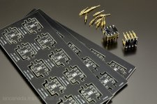
OPA1612 adapter PCBs
Both Greg and I like the sound signature of OPA1612 for the I/V STD especially for the balanced I/V stage (U1 and U2). So I designed this adapter PCB package to adapt the OPA1612 in SON-8 (my favorite package) which the P/N is OPA1612AIDRGR/T
OPA1612AIDRGR Texas Instruments | Integrated Circuits (ICs) | DigiKey
For other information, please see:
https://www.diyaudio.com/forums/pc-...i2s-dac-hats-raspberry-pi-87.html#post5821339
I have three of the PCB packages to share with the community for free (10 daughter PCBs per each package). Please send message to me with your shipping address if you are interested in them.
Ian
Attachments
@simon dart...
A VERY forgetful man.
I DID think about this... if you think you can remove / replace the clocks without harm, you could:
1. Pull them.
2. Use solder-wick to clean the pads.
3. Solder a small tag of copper foil onto the power pad on the board with the tag end going past the end of the pad for access.
4. Put a small piece of Kapton tape over the power pad and the copper foil tag on the board, leaving the excess end un-covered.
5. Solder a small tag of copper foil to the power pad on the clock with the tag end going 90 degrees to the board tag.
6. Solder the clock back down onto the 3 pads.
7. Solder a small piece of wire between the tags to power the clock from the board.
8. Cover the board pad tag with Kapton tape and solder the wire lead to power the clock from an external supply.
Easy... except for the microscopic soldering!
Greg in Mississippi
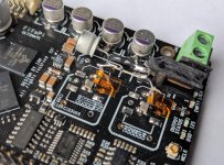
So after I got 3v3 rail number 5 sorted from my LiFePO4 board...
Yeah easy Greg.... NOT! But I did kind of manage it. Not super pretty as I had to cram in a connector on its side and some local decoupling but it's functioning. Too early to say how much of a gain but my gut is telling me that separate clock power is another worthwhile step up.
Attachments
Last edited:
A Quick help:
I had been using computer based transport using Jriver, Daphile, Jplay and so many other softwares with different results on my system. I just had a chance to look at what Ian has developed. After looking at the isolation and then async FiFo, I have simple question
Am I correct to believe that after using these boards all music playing tools (PC or RPi based) will sound the same?
My experience is no. When isolation and reclocking techniques became available, people expected they would eliminate upstream differences. But the real-world experiences have shown that not to be true.
In the setups where I use techniques such as this I find the differences are reduced, but not eliminated. Interestingly enough, this goes for both digital signal reclocking AND AC regeneration. I use both and find the results somewhat similar.
A good explainer of the current thinking for digital isolation by a high-end audio engineer can be found here:
Sonore opticalRendu - Page 27 - Sonore (Sponsored) - Audiophile Style
and here:
Sonore opticalRendu - Page 27 - Sonore (Sponsored) - Audiophile Style
John is referencing wired networking isolation and reclockng, but the same caveats carry over to digital audio signal isolation and reclocking where he has done a lot of related work.
Of course, your experiences, expectations, and mileage may vary.
Greg in Mississippi
Am I correct to believe that after using these boards all music playing tools (PC or RPi based) will sound the same?
It depends. If computer software does any resampling for any reason, and sometimes operating systems such as Windows will do it without telling you, and or if resampling occurs in a player such as HQplayer, that processing can and will change the bits and potentially make quite a large difference in sound quality. At other times it can sound slightly bad somehow, but it may be less obvious that the bits have been changed.
Then there are the mechanisms that Greg mentioned. There is ground common mode noise that can turn into a ground currernt. There is HF and RF noise from various sources in a computer that can couple into signal and ground connections, etc. And, of course there is what ESS refers to as 'transport jitter.'
Some people have believed that galvanic isolation and 'reclocking' could eliminate all such issues, but as you have already heard, it is really an issue of attenuation of noise that occurs. How much attenuation is necessary? Basically, until you can't hear any of effects of it, and can't measure much or any of it remaining.
Optical isolation is good because it eliminates current flowing between devices, especially if the optical cable is long enough to keep sending and receiving devices far enough apart such that electromagnetic coupling between devices is also strongly attenuated.
However, optical interfaces increase jitter. If there is too much jitter, ASRC may be needed to recover the signal before it can even be run through a separate 'reclocker.'
I would also point out that most reclocker circuits are not designed to work well at very high data rates. That's because propagation delay effects between clocks, dacs, and I2S signals are not usually accounted for to close tolerances. Delays through chips such as clock buffers, D-flip flops, etc., and delays of cable lengths, etc., typically work out well enough time aligned at low to moderate data rates, but can be fairly skewed relative to the timing constraints of high sample rate data and clock frequencies.
In addition, audio clocked around 50MHz or 100Mhz using LVCMOS devices starts to look a lot more like sin waves than square digital pulses. That makes data setup and hold timing constraints very hard to assure, say, as data is clocked into a dac chip. It can also make it complicated to know if reclocking is really working as intended.
Last edited:
I am planning to use lifepo4s in the full stack. I will not use Ian's lifepo4 power supply at the moment since I already have some BMS built. In the I/V board two individual 4 battery sets/bms will be used so inevitably the positive and negative rails will exhibit some voltage discrepancy. I wander how match detrimental this voltage difference will be.
It depends. If computer software does any resampling for any reason, and sometimes operating systems such as Windows will do it without telling you, and or if resampling occurs in a player such as HQplayer, that processing can and will change the bits and potentially make quite a large difference in sound quality. At other times it can sound slightly bad somehow, but it may be less obvious that the bits have been changed.
Then there are the mechanisms that Greg mentioned. There is ground common mode noise that can turn into a ground currernt. There is HF and RF noise from various sources in a computer that can couple into signal and ground connections, etc. And, of course there is what ESS refers to as 'transport jitter.'
Some people have believed that galvanic isolation and 'reclocking' could eliminate all such issues, but as you have already heard, it is really an issue of attenuation of noise that occurs. How much attenuation is necessary? Basically, until you can't hear any of effects of it, and can't measure much or any of it remaining.
Optical isolation is good because it eliminates current flowing between devices, especially if the optical cable is long enough to keep sending and receiving devices far enough apart such that electromagnetic coupling between devices is also strongly attenuated.
However, optical interfaces increase jitter. If there is too much jitter, ASRC may be needed to recover the signal before it can even be run through a separate 'reclocker.'
I would also point out that most reclocker circuits are not designed to work well at very high data rates. That's because propagation delay effects between clocks, dacs, and I2S signals are not usually accounted for to close tolerances. Delays through chips such as clock buffers, D-flip flops, etc., and delays of cable lengths, etc., typically work out well enough time aligned at low to moderate data rates, but can be fairly skewed relative to the timing constraints of high sample rate data and clock frequencies.
In addition, audio clocked around 50MHz or 100Mhz using LVCMOS devices starts to look a lot more like sin waves than square digital pulses. That makes data setup and hold timing constraints very hard to assure, say, as data is clocked into a dac chip. It can also make it complicated to know if reclocking is really working as intended.
@Markw4
How did you see a 100MHz clock looks like a sin wave?
Ian
- Home
- Source & Line
- PC Based
- IanCanada's Latest RPi GB Goodies Impressions... and your tweaks, mods and hints...