Not much Katana news out there, apparently. I've been working on different projects around Ian Canada's latest GB, so not a lot of time for Katana play in the last couple of weeks and likely not for the next 2-4.
BUT my 'audio friend' asked some questions about where to feed +-15V to bypass the on-board LDOs. I told him what others had done AND when he looked at it, he came up with what I think is a very good and clean way to do that... it's what I'll copy when I do it on mine.
He removed J32 (and the added 1000uF/35V cap) from the Opamp board and wired his +-15V feed (and ground) right there. At first, he dialed that back to +-14V... I reminded him that the Sparkos opamps are good with +-22V, so he'll take it back up to +-15V at some point.
By doing this, he not only uses the most easily-accessable direct path to feed the +-15V (and ground, of course), but he also bypasses the traces on the Microprocessor board AND does not have the outputs of the +-14V regulators being driven by his +-15V feed. Nice idea!
Here's his comments...
"Just got home. Took a quick listen to refresh. Power the Katana down. Pulled the micro controller off the stack.
Looks like 4-pin connector between the micro controller and the op amp board carries the output of the +/-15 VDC to regulated +/-14 VDC…
It is labeled J32 with Pin 1 as +14VDC, Pin 2 as -14VDC and Pins 3 and 4 as Ground.
Oh yea, that 1,000uF/35V cap that is “glued” to the top of the micro controller also connects to Pins 1 (+14VDC) and 2 (-14VDC).
So, not wanting any of what was on the bottom of the micro controller board - regs, caps, added glued down cap, etc. I pulled the J32 connector off the opamp board.
And, I added wires that I could then attach to my +/- Twisted Pear Placid HD power supply. I then adjusted the supply for +/- 14VDC and gave it a listen….
Ah…this is something that needs to move to the top of you list. Cleaner, clearer, quicker, more bass authority, blacker, quite a bit so, - just do it…."
When I do it, I'll attach my wires to the nearby +-14V local bypass caps as that helps prevent pulling off the pads (as those caps are attached at 2 ends, they are a LOT harder to pull off). AND locally strain-relief my wires.
I also suggested he do a quick try with/with-out the 1000uF/35V cap. He did so and had these comments:
"I hear ya on the 1,000uF/35V cap - nope. Tried it. Yuck. Just like always. When you have a CCS/shunt regged supply, you really just don’t want “anything” after it, or between it and the load in my experience."
I attached his pix below.
So there. What sounds to be another great Katana mod. And DO realize it is a mod... this is DEFINITELY taking your Katana into the 'user-modified' space and out of warranty! Not that I have any issues with this personally, but you might.
Anyone else have something to report?
Greg in Mississippi
P.S. My 'audio friend' just replied the other reason he went down to +-14V was to keep the offset low, as increasing to +-15V will likely change the output DC offsets. Let me check if I can share the offset setting info from Allo and if I can, I'll post it here.
Attachments
Last edited:
He removed J32 (and the added 1000uF/35V cap) from the Opamp board and wired his +-15V feed (and ground) right there.
How about removing the socket on the controller board instead, and wiring to the Opamps at the pins on J32? Or would that be a bad idea?
Edit: I'm asking this after looking at a picture of the controller board rather than the real thing, so maybe it's not even possible?
Last edited:
@jonners,
This is a good place to use 2 soldering irons, one on either side to heat up both pairs of leads at a time. When doing the original SQ mod according to Allo's instructions, I DID do this by heating up one side and using a pair of pliers to bend that side away from the pads. Careful, the plastic spacer is not very heat resistant. I'll see if I can get the PN for these from Allo.
Also doing what you suggested by removing the microcontroller board socket and wiring to the J32 connector pin bases would work well too.
Greg in Mississippi
Thanks Greg.
I have now wired my +-15V supplies this way, and without the !000uF/35V cap. First impressions are certainly 'cleaner, clearer, quicker', as noted by your 'audio friend'.
I measure the DC offsets with the +-15V supplies, and they are 0.3mV and 2.2mV.
Edit: Yes, better bass too. This is definitely the way to go!")
I have now wired my +-15V supplies this way, and without the !000uF/35V cap. First impressions are certainly 'cleaner, clearer, quicker', as noted by your 'audio friend'.
I measure the DC offsets with the +-15V supplies, and they are 0.3mV and 2.2mV.
Edit: Yes, better bass too. This is definitely the way to go!
Last edited:
Seems to me it would be better if doing that last mod to make it so you could switch back and forth between before/after. Then I would be possible to get a better idea of the magnitude of the change, how much was due to removing the cap, lowered resistance to the output stage board, etc., if any. I say if any because now that people are trying the mod knowing what to expect, its impossible to know how much the expectation influences subsequent judgments of sound quality. Also, not sure what cleaner, clearer, quicker actually means. Improved transient response, reduced distortion, or does it mean slightly more distortion of the type that gives the impression of more detail (i.e. 3rd harmonic).
I had already bypassed the LDOs on the controller board, so the only substantial change I just made was removing the connection to the controller board and removing the 1000uF cap. I wasn't really expecting much of a change from that, but it's really noticeable. I don't have the equipment to measure transient response, distortion etc. It now sounds to me like something that was holding the sound back has been removed, and I guess it's the cap that provoked the 'yuk' from Greg's 'audio friend' when he replaced it. Obviously, subjective descriptions like 'clearer' are going to mean different things to different people, and I don't think there's any way round that. I just know that this is the best I've yet heard from my Katana and I'm happy with it.
I would guess at least a part of what my 'audio friend' and jonners are reporting is due to not having the+-14V/+-15V rails also feeding the output of the non-powered +-14V LDOs. That can't be a good thing.
I've figured out how I plan to do this on mine in a manner that keeps my +-15V add-on board compatible with both stock and modified Opamp boards (and in this case, a Microprocessor board too). I have several Katana from the development process, so I'll modify 1 Microprocessor board and 2 Opamp boards and still have an entire stock Katana stack to compare against. I'll try to slot this in with the work on the gear I recently received from Ian's GB, which should work ok as my next activity is making up a number of power adapters... this is just another couple.
BUT I trust both assessments and suspect comparisons will be a moot point.
Greg in Mississippi
Probably a good amount of the improvement from this mod comes from routing the rails away from the on-board LDOs.
But removing/replacing the cap could be an upgrade in itself, too. I tried out a pair of Nichicon UKW for coupling the output of XRK's Pocket Class A amp to headphones a couple years ago, and disliked it.
My listening notes for a 25V 1000uF UKW:
"Reasonably pleasant, but the treble is quite dulled. Nicely engaging, slightly grainy mids. Bass extends low but is a little uncontrolled and surprisingly quiet for a 1000uF cap. Subpar detail and dynamics."
Mind you, this was a brutal test that made all the flaws in every cap quite obvious (I have a direct coupled headphone amp now). Rolling caps in a power supply, in my limited experience, reveals similar sonic signatures, but less dramatically. A 50V cap (as Allo used) probably sounds better, too.
Last edited:
I've had an interesting experience over the last couple of weeks. I configured a Katana Microprocessor board and 2 Opamp boards for direct +-15V, bypassing the Microprocessor board's +-14V LDOs, which BTW are confirmed as TPS7A19 positive and TPS7A3001 negative.
To retain use of my +-15V Sparkos regulator add-on board, I crafted a couple of adapters. First, I removed the +, -, & ground pins on the Microprocessor board. Then I used a piece of perf-board to craft an adapter that fit over the remaining pins AND carried those 3 pins. I soldered hookup wire to those pins on the adapater and routed the wires around the edge of the board on that side and down over to the connection points on the Opamp board. Of course, everything was appropriately insulated as needed.
To swap between the 2 different Opamp boards, I remove my +-15V Sparkos reg board, lift off the Microprocessor and the adapter off the remaining pins, remove the Opamp board, and reverse the process.
This allowed me to keep the same +-15V regulators and attachment points for this configuration, my stock 'developmental' Katana, and the beta version of a representative production Katana. This meant I can compare these setups in a somewhat controlled manner.
When I first did this, I also removed the 4-pin connector on the bottom of the Microprocessor board that formerly fed the +-14V / ground into the Opamp board. AND I removed the 1000uF/35V C, but not the 2 smaller 100uF C's. Note that because I had modified these Opamp boards back during the development of adding that additional filtering, mine were all connected on the Opamp board with minimum length leads. BUT that configuration would not fit in the existing case, so Allo repositioned the caps into the current production configuration.
I tried it. I could hear some improvment in the naturalness of the highs, but otherwise it was anemic and recessed sounding. HUH, not was my 'Audio Friend' and @jonners reported, AND not what I expected. I put it aside for awhile to start running in the Ian GB items I had just received, but listened to it again last weekend and if anything, the deficiences were more audible. I swapped in the stock-ish 'developmental' Katana I have and the sonics I was used to were back.
Hmmm... why? Grasping at straws, I considered:
- Maybe those Sparkos regs weren't so hot?
- Maybe my close-coupled very direct routing had some weakness?
- Maybe my use of 18G wire was inferior to the circuit board traces, though I was sure the wire had more copper cross-section?
AND then I hit on what I thought were the likely culprits... EITHER NOT having retained the ground connections on that 4-pin connector OR removing the 1000uF cap.
So I replaced the 4-pin connector on the Microprocessor board, but with Kapton tape under the +-14V pins to prevent them from connecting. AND put the 1000uF Cs back.
Note that I used different types of C's on those 2 different boards... One had the originally-recommended by Allo 1000uF/50V KW series Nichicon as the larger value and 100uF/35V KA Nichions as the smaller values. The other was an experiment I'd mentioned recently, using same-value United Chemicon KYB caps in each of those positions. I don't remember which caps Allo used for the production version... I know the 100uF ones were a different line than the KA series and I believe the 1000uF was different than the KW they originally recommended too.
With both of these changes the sonic deficiencies were fixed. NOW I had more finely deliniated (and slightly less promenent) highs along with better
definition and lower background noise across the spectrum, making it easier to listen too. AND sonic textures were more evident. NOW it was a definite improvement and another lift in the SQ of my modified Katana setup.
Why was mine different? Honestly, I can't say for sure. I suspect using a higher-spec 1000uF cap than Allo used in the final mod version was a factor.
AND I also suspect based on my read of the Sparkos datasheet that those 3 relatively large electrolytic caps are tolerated by the Sparkos regulators well, which may not be the case for the other regulators. At some point I'll try removing either the connector or the cap, try it, then replace it and remove the other. Also, going back and forth between these 2 Opamp boards, I suspect IF one can leave that cap in without causing problems for your regulator, the quality of the cap will be very important. I'm preferring the UCC KYB more now, it was a trade-off between these 2 cap sets before. IF your regulator tolerates significant output C well, that may be a good choice for trying Markw4's recommended film cap bank.
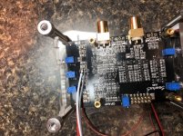
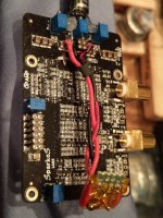
Pix attached include close-ups of the adapter board and how the adapter is fitted to the Opamp board.
BTW, the way I did this mod took a lot of 'craftsmanship'. I don't think I could have crafted the board without the years of experience I have in designing and building model airplanes. I don't recommend trying to duplicate this configuration unless you are good at this type of small, restricted access work.
Greg in Mississippi
To retain use of my +-15V Sparkos regulator add-on board, I crafted a couple of adapters. First, I removed the +, -, & ground pins on the Microprocessor board. Then I used a piece of perf-board to craft an adapter that fit over the remaining pins AND carried those 3 pins. I soldered hookup wire to those pins on the adapater and routed the wires around the edge of the board on that side and down over to the connection points on the Opamp board. Of course, everything was appropriately insulated as needed.
To swap between the 2 different Opamp boards, I remove my +-15V Sparkos reg board, lift off the Microprocessor and the adapter off the remaining pins, remove the Opamp board, and reverse the process.
This allowed me to keep the same +-15V regulators and attachment points for this configuration, my stock 'developmental' Katana, and the beta version of a representative production Katana. This meant I can compare these setups in a somewhat controlled manner.
When I first did this, I also removed the 4-pin connector on the bottom of the Microprocessor board that formerly fed the +-14V / ground into the Opamp board. AND I removed the 1000uF/35V C, but not the 2 smaller 100uF C's. Note that because I had modified these Opamp boards back during the development of adding that additional filtering, mine were all connected on the Opamp board with minimum length leads. BUT that configuration would not fit in the existing case, so Allo repositioned the caps into the current production configuration.
I tried it. I could hear some improvment in the naturalness of the highs, but otherwise it was anemic and recessed sounding. HUH, not was my 'Audio Friend' and @jonners reported, AND not what I expected. I put it aside for awhile to start running in the Ian GB items I had just received, but listened to it again last weekend and if anything, the deficiences were more audible. I swapped in the stock-ish 'developmental' Katana I have and the sonics I was used to were back.
Hmmm... why? Grasping at straws, I considered:
- Maybe those Sparkos regs weren't so hot?
- Maybe my close-coupled very direct routing had some weakness?
- Maybe my use of 18G wire was inferior to the circuit board traces, though I was sure the wire had more copper cross-section?
AND then I hit on what I thought were the likely culprits... EITHER NOT having retained the ground connections on that 4-pin connector OR removing the 1000uF cap.
So I replaced the 4-pin connector on the Microprocessor board, but with Kapton tape under the +-14V pins to prevent them from connecting. AND put the 1000uF Cs back.
Note that I used different types of C's on those 2 different boards... One had the originally-recommended by Allo 1000uF/50V KW series Nichicon as the larger value and 100uF/35V KA Nichions as the smaller values. The other was an experiment I'd mentioned recently, using same-value United Chemicon KYB caps in each of those positions. I don't remember which caps Allo used for the production version... I know the 100uF ones were a different line than the KA series and I believe the 1000uF was different than the KW they originally recommended too.
With both of these changes the sonic deficiencies were fixed. NOW I had more finely deliniated (and slightly less promenent) highs along with better
definition and lower background noise across the spectrum, making it easier to listen too. AND sonic textures were more evident. NOW it was a definite improvement and another lift in the SQ of my modified Katana setup.
Why was mine different? Honestly, I can't say for sure. I suspect using a higher-spec 1000uF cap than Allo used in the final mod version was a factor.
AND I also suspect based on my read of the Sparkos datasheet that those 3 relatively large electrolytic caps are tolerated by the Sparkos regulators well, which may not be the case for the other regulators. At some point I'll try removing either the connector or the cap, try it, then replace it and remove the other. Also, going back and forth between these 2 Opamp boards, I suspect IF one can leave that cap in without causing problems for your regulator, the quality of the cap will be very important. I'm preferring the UCC KYB more now, it was a trade-off between these 2 cap sets before. IF your regulator tolerates significant output C well, that may be a good choice for trying Markw4's recommended film cap bank.
Pix attached include close-ups of the adapter board and how the adapter is fitted to the Opamp board.
BTW, the way I did this mod took a lot of 'craftsmanship'. I don't think I could have crafted the board without the years of experience I have in designing and building model airplanes. I don't recommend trying to duplicate this configuration unless you are good at this type of small, restricted access work.
Greg in Mississippi
Attachments
Hi Greg,
I happened upon the datasheet for those Sparkos Regs. I think the source of your sonic changes is the low ESR of the caps on the Opamp board itself. I have the exact same issue with my Super-regs as they are of similar design (series pass) and are different in behaviour to LDO type regulators.
The Sparkos Datasheet warns against using low ESR caps on the output. Specifically it recommends 100uF Electrolytics of circa 65 mOhm ESR. The pair of 22uF ceramic caps on the opamp boards will be significantly lower than that, likely lower than 10 mOhm ESR.
The datasheet states:
"Output capacitors placed close to the regulators
output that are of ceramic or film type are not
recommended due to their extremely low (sub
10mΩ) ESR. Capacitors of this type will degrade
the phase margin of the voltage regulator and
worsen the transient response and ringing. Utilizing
an electrolytic or tantalum output capacitor is
preferred due to their higher ESR of several tens of
mΩ as opposed to sub 10mΩ."
It goes on to say that the reg will nonetheless remain stable in spite of low ESR on its output but phase margin will be degraded. What you actually get is a resonant noise peak at the point where the Q of the resultant tank circuit is at its highest. this will show up as ringing on transient loads, quite possibly within the passband of the opamp filters on the board at a frequency where the circuit PSRR is also reduced.
Adding the additional large cap slows the response of the reg down and overdamps the output tank circuit in much the same way as increasing the ESR but it rather wastes the transient regulation capability of the good Sparkos regs. For every (total) load capacitance there is an optimum ESR.
The 22uF X5R ceramics are a real no-no for my super-regs too but at the moment mine are some 30cm from the board and the consequential ESR and local caps on the regs reduce the problem. Ideally the regs should be up close and the ESR vs total capacitance tuned with the effective output inductance of the reg to give critical damping. Interestingly enough the same Sparkos reg data sheet shows a circuit for testing the transient response of the reg that would allow this tuning to be done (Figure 7 if you have a copy). I plan to use this circuit with the existing load capacitance to measure the frequency of ringing and thus deduce the regs output inductance under load. From that I can deduce the minimum capacitance and ESR required for the best transient response, rather than overdamping and losing (some) regulation.
We can add some figures to this:
Sparkos recommend 100uF with 65mOhm ESR. assuming that is for critical damping, that approximates to 0.1mH of effective output inductance. So from Q=1/R X root L/C, if you have a total of 22uF capacitance you will need it to have 100mOhm of ESR and if the total is 1000uF it will need just 14m Ohm ESR. 1000uF makes it nearly critically damped as the ESR required gets closer to that of the onboard 22uF ceramics. The frequency of the noise peak with just 22uF will be 72kHz. For 100uF it will be 50kHz and for 1000uF it will be 15kHz. The peak will get smaller and at a lower frequency as you raise the capacitance, but the regulation will be poor above that frequency as it will be dependant upon the capacitor only. The good thing is that the circuits own PSRR will be much better at 15kHz and that 1000uF seems to be about the optimum figure for the circuits existing ESR of circa 10mOhm but with poor regulation bandwidth.
In my opinion it would be best if the existing on board caps had sufficient ESR of their own, or given that this is a class A circuit, the existing caps could suffice and a series 0.1 ohm resistance should not degrade performance but remove the noise peaking and allow best transient response. Why not try removing all caps apart from the 22uF ceramics at the base of the power input connector on the opamp board and then connect the Sparkos power through a couple of 0.1 ohm resistors?? When I tune my regs for the circuit I will try that.
Also if the regs are each allowed to do their job the load capacitance total should be to 0 volts rather than rail to rail IMHO.
FWIW LDO type regs such as the LT3042/5 require low ESR to reduce their gain and the load capacitance also reduces their regulation at high frequencies to avoid instability. This makes them easy to apply and use. Unfortunately they are outperformed on output noise, output impedance, line and load regulation by discrete series designs such as the Super-regs and Sparkos.
This is the limit of my understanding of these mechanisms thus far ….
John
Last edited:
Sorry I haven’t posted for awhile. I’ve been busy setting up and trying many of the various combinations one can run the gear from Ian’s recent GB. Getting some good sound and working up a few tweaks and mods.
Back on topic, first, many thanks to @John Lukins for your post on what I was likely hearing when I tried directly connecting the regulated +-15V to the Opamp board and bypassed the LDOs on the Microprocessor board. That was an excellent analysis and a very informative and educational post. It is clear that you have forgotten more on the subject of optimal output C size and type on the performance of various regulators than I ever knew!
What makes the situation a bit more complex is that I already had a 680uF United ChemiCon KYB series cap at the output of each Sparkos regulator, roughly a centimeter away. AND I use about 8cm of wire from the regulator board connectors to the +-15V input point on the Opamp board, which based on your comments is not going to add a sufficient amount of R & L to buffer the regulator from the 1000uF cap across the +-15V rails.
The next thing to try here is to replace the 3 caps across the rails with caps from each rail to ground.
Again, many thanks!
Then, in preparation to compare the gear from Ian’s GB to the Katana, I moved my reference Katana setup using the SQ board and mods applied as outlined in my posts above into my other audio system, my downstairs system. It is VERY similar in many ways to my upstairs system where I ran the Katanas initially and during Allo’s refinement of the design.... same high-quality AC filtering and regeneration, same amps, same power cables, and very similar vibration control, digital setup power supplies, volume control attenuator, audio cables, and speakers. One possibly significant difference in the digital power supplies... the upstairs is the one I described in a post early in this thread, the downstairs is very similar, but instead of using 2 dual-secondary Hammond 229-series transformers for the 4 main digital rails (roughly 12V raw DC, requiring regulation for or at the digital sources), this one uses 4 fairly over-sized toroidal transformers, provide both a lower output supply impedance due to the higher current capability and better separation between the rails since none have a shared transformer in this setup.
The main material difference is that the upstairs system is in a fairly large room with significant and well-placed acoustic damping on the walls and floors along with a good location for the listening position well-away from both the speakers and the rear wall. The downstairs system is in a much smaller, almost square room with no wall acoustic damping and little on the floor and the listening position is much closer to the speakers (fairly large planar magnetics, again similar to those upstairs) and almost in near-field.
The upstairs setup shows gear to its best, the downstairs setup requires gear to be performing at its best to sound good.
The Katana replaced my highly modified SDTrans384 (my best I2S source) and highly modified Soekris DAM discrete R2R DAC combo, which has been my daily listening setup in that downstairs system.
To my ears, in these setups, and with my listening preferences, the Katana did very well in comparison, with better definition, dynamics, and extension while coming very close to the natural presentation of the R2R DAC (I attribute that to the Rasmussen pre-I/V filtering mod, I've heard that same effect when I've used it before). AND the Katana was on a stock RPi versus the modified SDTrans384 of the Soekris, so the master-mode setup on the RPi is working well in comparison to the intrinsically better SDTrans384 as a source. When I transfer the Katana onto one of my linear-regulated modified RPis (replacing the DC-DC converters) I expect to hear another lift in SQ, based on what I've heard with other DACs on those.
IMHO, the Katana fared well against my ‘reference’ modified SDTrans384 -> modified Soekris DAC. AND it is nice to use the RPi player where I have access to MUCH more of my library selectable via an app instead of the limited selection of music from my library on SD cards for a player with very limited functionality.
I thought those of you out there in Katana-user land might want to hear this!
Greg in Mississippi
Last edited:
hello,
I'm nood and french people so please be tolérent
I read all the post and a thank everyone because a learn a lot.
for nood people like me who are looking for power supply with good value price/quality a purpose this one
for isolator: Module d'Alimentation lineaire DC regule LT1083 1.2V / 19.5V 2.5A - Audiophonics
for DAC and microcontrol: Module d'alimentation lineaire LT3042 pour XMOS
for +/- 15v Module Alimentation Lineaire Regule Double LM317/337 + TL431 +/- 5V a 37V 1.5A - Audiophonics
for cable: Cable XH 2.54mm Femelle Blinde 1 Connecteur 3 Poles vers Fils Nus Gris 30cm (Unite) - Audiophonics
I test it and it's work perfectly.
Have a good ... song
@Elba,
Thanks for your comments and great links. Appreciate that!
Everyone else, I'm contemplating several more mods and wanted to share them in case anyone is more energetic than I and will try them faster than I.
The first one is just simply soldering a wire link across the jumper on the Isolator 1.2 that sets it to get 5V from the DAC board. I don't expect any significant changes from this.
The second is to restructure the added caps from across the +-15V rails to a rail-to-ground setup. I'm planning to start with a 1000uF caps from each rail to ground at the +-15V/ground connector and another pair connected to the 2nd set of caps out from that connector, likely 300uF-700uF units. Will report the results.
The third is to level the listening field between the Katana and Ian's GB gear in my upstairs system. As I mentioned above, all sources in that system feed an S&B TX102 transformer volume control (TVC) which accepts either SE or Balanced outputs and feeds them to my amp (in this case one with balanced inputs). I've been feeding the TVC via the SE RCA jacks on the Katana, which adds an additional summing opamp in line. As good as the Sparkos are, I'm of the camp that reducing stages is generally a good thing. AND since the Katana has fully filtered balanced outputs, I'll connect a 2nd pair of RCA jacks there for use in the upstairs setup. I do basically the same thing with the 2 Ian GB IV stages that also use a summing opamp to generate the SE output, connecting RCAs to the balanced outputs to bypass that extra stage.
Will also report what I hear with this too.
Greg in Mississippi
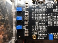
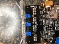
I hard-wired across the jumpers (DAC board and Isolator, I'd forgotten about the latter) today along with replacing the 3 stock-ish rail-to-rail Cs with 4 rail-to-ground Cs.
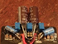
For the Cs, I used a pair of 1500uF/16V United ChemiCon KYB series (yes, I know 16V on a 15v rail is cutting it close!) and re-purposed the pair of 100uF/35V Nichicon UKA from the original trial of this mod. See attached pix.
Initial impressions are positive. I detect an increase in definition top to bottom due to deeper inter-transient silences and blacker-backgrounds. I want to give the modified board some time to run-in and then go back and forth... I did this on a 2nd opamp board, so I can swap and compare pretty easily. I honestly was not expecting what I heard.
I've also been thinking more about using the balanced outputs. One thing I did not mention to many others during the refinement period on the Katana was that before Allo added the different Cs across the various rails to lower the noise on each AND changed the filter pole in the balanced-to-single-ended summing stage, listening at moderate levels would induce ringing in my ears. This stopped with the final electrolytic Cs and the just previous output filter C adjustment. That was when I could finally get real excited about the Katana.
I'm bringing this up because as I listen to the various output stage options of Ian's GB gear (including a couple of prototype IV stages, one using the OPA861 and the other the OPA1632), I am also hearing that the filtering poles are set too high for my ears and preferences. I do need to be clear, this is a personal hearing and preference thing, AFAIK no one else commented on the filtering being set too low in the early Katana (and on Ian's GB gear).
I've experimented with the filtering on Ian's outputs and have them in the right ballpark for my ears and preferences, which is about the same level of filtering as on the final Katana.
BUT knowing how the Katana filtering is structured between the I/V stage, balanced outputs, balanced-to-single-ended summing stage, and single-ended outputs, I suspect that I will find too low of a level of filtering from the balanced outputs as currently implemented for my hearing and preferences.
We'll see once I pop-in some connectors and run a Katana into a balanced attenuator and my amps' balanced inputs.
More as I do the above AND as the rail-to-ground caps get some run-time.
Greg in Mississippi
Attachments
Last edited:
Hi Greg Stewart,
Thanks for your topic. I learned a lot from this topic and try on my Katana DAC. It can help improve the SQ of DAC. I used 3xLT1963 to a Mezzaline pcb for Pi 3 psu.
Mezzanine Power board<br>for Raspberry Pi.
I also try the ISOLATOR V2 but it not better than Mezzanine, so I remove it.
A 5V 2xLT3042 psu for Microcontroler. I try to separate 5V for DAC and MC but it got error (LED on MC flashing and not stop) although I note to power sequence MC-DAC-Pi. So now, I only used 5V MC and Mezzanine for Pi.
Another things should be consider is quality of +_15V psu and which almost power Capacitor effected to SQ. I used Salas Ultra Bib 1.3 and I try to replace some power caps such as Nichicon Gold tune, Rubicon, Mundorf and they effected to sound stage even laid back or forward, frequency range...etc. Let's enjoin your diy game.
Last edited:
Hi All,
Please see my short report about Salas designed PSUs on Katana DAC here (post #91): L-Adapter
I made two clips for YouTube and unfortunately only one is available for US viewers. Second one was blocked by YouTube due to some copyrights in US, but it is still available for the rest.
Here is the one that is blocked in US: YouTube
Second one is available from L-adapter thread.
Last edited:
Been too quiet here...
@anhton82 and @alexkosha,
Thanks for your comments and keeping this thread alive! Alex, especially thanks for your tip on Salas L-Adapter... I'll have to give this a try!
Just a few recent upgrades to my Katana setup and I'm quite happy with them...
First, I added a 3rd iFi iPurifier to the setup where I have the Katana playing. I already have a fairly extensive and effective AC filtering and regeneration regime in place, not only at my systems' AC inputs, but also at various noise producing AC-powered items in the house. BUT I could hear the iPurifier doing its magic reducing the almost-always-present high-frequency hash on today's SMPS-dominated AC power lines. I now have 3 in each system and they are both better for them.
Second, a few months back a mentioned trying a pair of 6||LT3045 boards from MPAudio replacing the 3||LT3045 ones on my 5V DAC and Microprocessor board supplies. While I liked what I heard, it was a tiny bit of a mixed bag, mostly because I had optimized those 6||LT3045 boards for use as 15V supplies to try on the Opamp boards. A few weeks back I finished up a couple 5V versions and have had them running since. No longer a mixed bag, these are definite upgrades to the 3||LT3045 boards. At almost 150 Euro each, these are not low-cost upgrades, but the benefits in dynamics, overall definition and especially treble purity and clarity are very worthwhile. Still, I'm very curious how they will fair against the soon-to-be-released Allo Shanti dual 5V supply. Will report back once I have one here and broken-in.
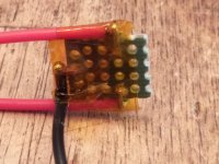
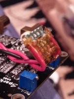
Third, although I haven't tried them yet, my 'audio friend' and I got some 'ideal diode' boards from one of the GBs here on DIYAudio. While I haven't had a chance to try them yet, he put one in the supply feeding his Katana's DAC board. No full report yet, but his comment was 'sonically gobsmacked'. See attached picture of the board in his supply.
So another upgrade path worth looking at.
Anyone else have anything interesting to report?
@anhton82 and @alexkosha,
Thanks for your comments and keeping this thread alive! Alex, especially thanks for your tip on Salas L-Adapter... I'll have to give this a try!
Just a few recent upgrades to my Katana setup and I'm quite happy with them...
First, I added a 3rd iFi iPurifier to the setup where I have the Katana playing. I already have a fairly extensive and effective AC filtering and regeneration regime in place, not only at my systems' AC inputs, but also at various noise producing AC-powered items in the house. BUT I could hear the iPurifier doing its magic reducing the almost-always-present high-frequency hash on today's SMPS-dominated AC power lines. I now have 3 in each system and they are both better for them.
Second, a few months back a mentioned trying a pair of 6||LT3045 boards from MPAudio replacing the 3||LT3045 ones on my 5V DAC and Microprocessor board supplies. While I liked what I heard, it was a tiny bit of a mixed bag, mostly because I had optimized those 6||LT3045 boards for use as 15V supplies to try on the Opamp boards. A few weeks back I finished up a couple 5V versions and have had them running since. No longer a mixed bag, these are definite upgrades to the 3||LT3045 boards. At almost 150 Euro each, these are not low-cost upgrades, but the benefits in dynamics, overall definition and especially treble purity and clarity are very worthwhile. Still, I'm very curious how they will fair against the soon-to-be-released Allo Shanti dual 5V supply. Will report back once I have one here and broken-in.
Third, although I haven't tried them yet, my 'audio friend' and I got some 'ideal diode' boards from one of the GBs here on DIYAudio. While I haven't had a chance to try them yet, he put one in the supply feeding his Katana's DAC board. No full report yet, but his comment was 'sonically gobsmacked'. See attached picture of the board in his supply.
So another upgrade path worth looking at.
Anyone else have anything interesting to report?
Attachments
Last edited:
@Greg Stewart
- Balanced output: Did you finally have the chance to try the balanced output? If so, how do you like it? On my end, I've got to try a set of
Oyaide TUNAMI TERZO XX V2 XLR cables
Review on 6moons
The SQ was noticeably better than with my home made XLR cables built from Neutrik connectors and Mogami W2534 wire.
Given the improvement, I decided to replace the XLR connectors and hookup wires with better quality ones in order to squeeze the most SQ out of it. The problem is that after soldering and unsoldering a few times, the copper soldering rings on the board almost disappeared on the right channel so I can’t seem to solder any wires there anymore on the balanced output I guess I could build a rebalancing circuit connected to the unbalanced output as @Markw4 suggested but I was wondering if there could be another temporary option in the meantime? Here’s what I was thinking:- find the nearest spot on the signal path where I could solder my hookup wires
- scratch the surface to get to something I could solder on (if the output board is multi-layer?)
- ‘Ideal diode’ board: Do you have a reference on how to build it?
- 5VDC PSU: I am considering to replace my iPower PSUs for MC and DAC boards with LPS. I can’t afford your latest test with 2 x MS-HPULN PS so I was wondering which of the following options you think would be best to try:
- 08uv-ultralow-noise-dac-power-supply-regulator Been out of stock for a while
- 0.56uV Ultralow noise DAC power supply regulator 3.3/5/7V 2A
- [URL="https://www.mpaudio.net/product-page/md-hpuln-ps”]md-hpuln-ps[/URL]
- some other options?
- Home
- Source & Line
- PC Based
- Getting the best out of Allo.com's new Katana DAC...