Hi guys - I'm not nearly as knowledgeable as the rest of the folks on the thread, but would like to participate. Greg, I hope you will entertain the idea of some education happening on your thread ") .
.
So during Katana's development, I, too was working on my own little project. It all came together over the last two weeks, and I'm pleased with the results.


So now back to the issue of powering. It appears as though there are a few basic things needed for an optimal powering solution:
1) Linearity. The power source should be able to provide peak current demand at the expected voltage. If the power source runs out of current, either the voltage drops or components heat up (or both), each independently having a detrimental effect on sound and we don't want to rob the music of its dynamics. This is likely most impactful for analog stages where peak current usage might spike during dynamic segments. Addition of buffer caps can help, but they should be placed right before feeding the power. i.e. having a low PSRR regulator isn't a replacement for having a buffer after it. Is this assumption correct?
2) Low noise. I understand there are two categories of noise: one on the voltage line, caused late in the supply by rectifiers and regulators, and second on the ground. Perhaps one affects the other. New regulators like the LT3045 has very low noise in category one, but cannot eliminate ground noise. Is this the right way to think about it?
3) Regulation. Chips operate efficiently at a variety of voltages including 3.3v and 1.5v. To power these, the containing circuit often contains further regulation, but with little thermal protection since it expects an input at a given voltage (say, 5VDC). A low noise regulated power source allows everything to operate in a calm, predictable environment. Does linearity matter more than this?
All of this brings me to #4, Isolation.
A noisy ground is the same as a noisy power supply for all intents and purposes, is it not? It seems to be the principle behind the Isolator where there are clean and dirty grounds.
Now, if I understand the spirit of this discussion, it is to determine an optimal powering solution to provide 2x 5V supplies (Isolator/Rpi and MCU) and a +/-15V in a practical manner (i.e. commensurate with the cost of the Katana stack. Ideally ~$500)
If so, I wonder, would our efforts be better spent on determining a single transformer technique with a focus on isolating grounds? Perhaps using DC DC converters?
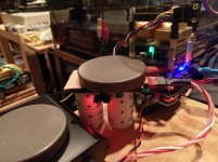
Personally, I cannot fit another transformer in that chassis, so I have to find a creative way to bring +/- 15V. I've been eyeing Jan Didden's SilentSwitcher for over a year now, and finally pulled the trigger today. I'm hoping it's at least better than the MCU sourced 15. Plus I get a bonus 0.5A 5V source, so I can play with the "quad" power technique (Isolator/5V, Katana/5V, MCU/5V, Output stage +/-15V). This is how it is setup now:

.So during Katana's development, I, too was working on my own little project. It all came together over the last two weeks, and I'm pleased with the results.
So now back to the issue of powering. It appears as though there are a few basic things needed for an optimal powering solution:
1) Linearity. The power source should be able to provide peak current demand at the expected voltage. If the power source runs out of current, either the voltage drops or components heat up (or both), each independently having a detrimental effect on sound and we don't want to rob the music of its dynamics. This is likely most impactful for analog stages where peak current usage might spike during dynamic segments. Addition of buffer caps can help, but they should be placed right before feeding the power. i.e. having a low PSRR regulator isn't a replacement for having a buffer after it. Is this assumption correct?
2) Low noise. I understand there are two categories of noise: one on the voltage line, caused late in the supply by rectifiers and regulators, and second on the ground. Perhaps one affects the other. New regulators like the LT3045 has very low noise in category one, but cannot eliminate ground noise. Is this the right way to think about it?
3) Regulation. Chips operate efficiently at a variety of voltages including 3.3v and 1.5v. To power these, the containing circuit often contains further regulation, but with little thermal protection since it expects an input at a given voltage (say, 5VDC). A low noise regulated power source allows everything to operate in a calm, predictable environment. Does linearity matter more than this?
All of this brings me to #4, Isolation.
A noisy ground is the same as a noisy power supply for all intents and purposes, is it not? It seems to be the principle behind the Isolator where there are clean and dirty grounds.
Now, if I understand the spirit of this discussion, it is to determine an optimal powering solution to provide 2x 5V supplies (Isolator/Rpi and MCU) and a +/-15V in a practical manner (i.e. commensurate with the cost of the Katana stack. Ideally ~$500)
If so, I wonder, would our efforts be better spent on determining a single transformer technique with a focus on isolating grounds? Perhaps using DC DC converters?
Personally, I cannot fit another transformer in that chassis, so I have to find a creative way to bring +/- 15V. I've been eyeing Jan Didden's SilentSwitcher for over a year now, and finally pulled the trigger today. I'm hoping it's at least better than the MCU sourced 15. Plus I get a bonus 0.5A 5V source, so I can play with the "quad" power technique (Isolator/5V, Katana/5V, MCU/5V, Output stage +/-15V). This is how it is setup now:
Last edited:
1) Linearity. The power source should be able to provide peak current demand at the expected voltage. If the power source runs out of current, either the voltage drops or components heat up... Is this assumption correct?
The power source tries to maintain close to a constant output voltage, regardless of current draw by the load. However, the voltage always drops some, it has to in order for the power supply to adjust for the current draw. We just want to keep the voltage drop very small and well behaved over time.
2) Low noise. I understand there are two categories of noise: one on the voltage line, caused late in the supply by rectifiers and regulators, and second on the ground. Perhaps one affects the other. New regulators like the LT3045 has very low noise in category one, but cannot eliminate ground noise. Is this the right way to think about it?
Noise can be a complex subject, but one could talk about noise sources that come before a regulator, noise produced by the regulator, and noise produced in the load. Noise before the regulator can include anything going all the way back to the power station generator.
LT3045 is not perfect in terms of noise. The graphs are impressive, but rise at low frequencies and are not even shown below 10Hz. Although 10Hz is lower than music pitches, it can affect distortion of higher frequency sounds in some cases.
Ground noise is caused by current flowing in the ground path be it a wire, a ground plane, or whatever. There is always resistance in the ground path and any current flowing will have an associated voltage across the ground resistance. If that voltage is undesirable, which it usually is, then it would be classified as ground noise.
3) Regulation.
Regulation doesn't mean what you think. It has to do with how much voltage drop it takes at a regulator output for it to supply needed current to the load.
A regulator that experiences very little voltage drop associated with increased current draw is said to have good regulation.
All of this brings me to #4, Isolation.
A noisy ground is the same as a noisy power supply for all intents and purposes, is it not?
It can produce similar undesirable effects.
Regarding the Katana isolator, I would say it probably works in multiple ways. It probably partly acts as an electrostatic shield between the RPi and the Katana board. It also removes noise from various signals coming from RPi, including for I2S and I2C. The noise might otherwise inadvertently couple into sensitive circuitry and or directly affect the timing of time critical signals.
Last edited:
Markw4,
Humor me, and allow me to do it of "out loud" thinking here...
I read with interest your remarks on the use of the LT3042 regs and, in particular, you suggest using the 1/f configuration for DACs as the low frequency noise for these regs is not the best otherwise...
That pointed me in a direction. So, I've made some sonic comparisons. Powering a BOSS DAC, v1.2, I compared a regulator configuration having an LT3042 with a pass transistor (NOT a 1/f configuration, mind you) to a regulator using a TPS7A4700 - both set for 5 VDC. Just looking at the spec sheets, which one do you think might win out in terms of low frequency noise? And, which one do you think won out sonically?
Not trying to bait you here, please don't take it that way. Just trying to understand your suggestion and examine where you're coming from.
Thanks!
jrocker,
I don't think we know everything about why dacs sound better or worse with different power supplies. However, there has been kind of a love affair gone bad within some of the groups at diyaudio regarding LT34x and dacs.
Looking at LT304x regulators, they have noise than increases at LF which could cause some intermodulation issues in some dac architectures. They also may have a tendency to ring with some kinds of loads if excited by sudden load current changes. I think KSTR summed up the thinking on that here: https://www.diyaudio.com/forums/power-supplies/311453-tried-chinese-lt3042-board-4.html#post5561404
I don't think we really know how much those things are issues with dacs and for very sensitive listeners. If they are problems, we should find out. Otherwise, it seems like the regulators should work pretty well.
On the other hand, it may be these dacs we are working with simply will sound better with something more like Super Regulators.
My own experimental dac is running on a mix if different approaches including one LT304x.
We also have some people in this thread who seem to think LT304x work great for RPi.
Lots of opinions and very little data. Some guesses that might turn out to be right or wrong. You never know.
In particular for something like Katana there is the very sensitive AVCC power supply. People use all sorts of things for that, but there is reason to think that very LF noise might be a problem there since AVCC has zero PSRR, and it is multiplied and added to the audio output signal. LF intermodulation of audio could be an audible issue there.
Anyway, I think we just need to dig in and start trying things. My post was quite speculative, but if tried I think maybe some of the objections people have had with LT304x might be improved. Or maybe not. And even if it did help it might turn out not to be the only problem. However, the LT304x data sheet suggest that while increased load capacitance doesn't necessarily help, it doesn't necessarily hurt either. With the loads these dacs present I am willing to make a guess we won't see ringing problems and that even very fussy people might be satisfied. There is still an element of guessing involved, of course.
Alternative regulators such as TPS7A4700 did not come into consideration in this case. There are lots of possible choices, and some reasons to suspect that if LT304x can't be made satisfactory to more picky listeners, then probably making a bigger change in the direction of trying Super Regulators might be more revealing/rewarding.
Last edited:
@absolutk,
First, I hope this thread is all about education. I know that there are many on here with MUCH more knowledge and experience than I. I hope we can all learn from them and everyone else here.
IMPRESSIVE PROJECT! Looks like you've been working on it for awhile. AND it is nicer looking than anything I do.
A couple of quick observations, based on my experience...
- I see you are planning to use Fiber Media ethernet links to provide ground isolation. I assume these will be in the ethernet connection going into the RPi. I also see you are planning to power them from the same output. That will reduce the amount of isolation between them and thus reduce their effectiveness, due to both sharing a ground connection and sharing a common power source. Better to use an entirely separate power supply for the upstream one and this supply to only power the downstream one just before the RPi. I use FMCs too, but to preserve the isolation between them, I not only use separate supplies, but also use separate AC circuits in my house for the upstream computer and networking-related gear versus the downstream FMC, player RPi, digital processing, DAC, and other audio equipment.
Also, some have reported mixed results with FMCs. People who know a lot more than I about networking equipment used in audio systems say that the wired to optical ethernet conversion and back introduces jitter into the process and that may reduce SQ. To try to combat this, I, like you are planning, use good linear-based supplies on my FMCs with my best FMC and supplies at the downstream end. For the downstream FMCs, the best I've tried so far are the Delock from Germany.
- Though I haven't tried one for the +-15V supply on the Katana, a Silent Switcher to produce the +-15V Opamp board supply may not produce any better results over the on-board +-15V DC-DC converters. In architecture, they are very similar. I even suspect Allo's on-board implementation may better the Silent Switcher based on my listening tests with the SS on a different RPi DAC that required +-15V.
- Isolation between different power rails is improved by separating the source power between the different output rails as much as possible. Separate AC-DC rectification and filtering is good, separate secondaries on a single or otherwise shared transformers is better, completely separate transformers per rail is even better. You may not be able to implement this now, but consider that for a possible future upgrade. Also, using a Silent Switcher powered off one of these rails MAY introduce noise from the DC-DC conversion process back into the source raw DC where it can be coupled into the 5V feed.
AND having said this, your setup should work as planned.
@Markw4 & @jrocker, great comments & very provocative discussion. I'll comment when I have more time. I'm excited to see exploration & discussions of tradeoffs betweeen different options & philosphies here.
Gerg in Mississippi
Sorry to pollute...but great discussion .
We measured our DC/DC convertor and we have very low noise coming out if it. We used a trick (RC snubbers across all switching outputs and that reduced the output noise a lot)..and of course multiple parallel caps.
Still I agree..any DC/DC convertor will introduce some noise in the GND and that its not easy to get rid of.
On the DC/DC convertor , we have added a electrolytic but I think its clear that more capacitance there will have a clear effect on SQ . In fact I can measure some oscillation before LDO (dual rail) that was reduced with the added cap but its still at around 1.5mV. After the LDO though , we are at Gnd noise..
I also fully agree with LDOs like LT3042 (or any for that matter) for AVcc...yes they can ring and yet we used LDOs.However we used the supercaps on the avcc , most of power comes from them and they also have some ESR that will dampen most oscilations
Last edited:
First, @Markw4, some thoughts on your thoughts on @absolutk's thoughts...
I would add to linearity the dynamic behavior of the regulator. To what extent does it track the current needs of the fed circuitry linearly? To what high-frequency cutoff? How does it behave after that cutoff? Does it track symmetrically? Does it have sufficient headroom to track all current needs and not 'clip' current and sag voltage. Does it do that clipping gracefully or hard? Does it ring or exhibit any other unstable behaviors? This is not an exhaustive list either, just scratching the surface of how regulation can go wrong.
As I understand it, noise in a regulator output is also caused when the regulator does not perfectly track the current requirements or where the non-linearities cause bad behaviors such as ringing.
Then, my view on isolators such as sold by both Allo and Ian Canada for use between an RPi and downstream digital processing and DACs is a bit contrary to popular beliefs. First, IMHO, while they are good in breaking the ground connection between the input side and output side, they don't remove or correct waveform anomolies in the input signal. ANY ground noise present at the input of the isolator chip is faithfully reproduced on the output. That is my theory on why you can still hear improvements in the power fed into the RPi (or any other I2S source) AFTER adding an Isolator.
Then the chips used in the Isolators add jitter to the signal as part of the transmission process. That is why it is good to have a reclocking occur before feeding the signals into your D to A conversion device/process. Allo AFAIK doesn't do this before the ES9038Q2M in the Katana. THEY DO get great results. So in this case, breaking the ground connection is likely of greater benefit than the Isolator-added jitter. BUT adding flip-flop-based reclocking to the I2S signals right before the DAC chip MIGHT be a possible further improvement for a Katana 2.0. Allo also made the master-mode Boss 1.2 work well VERY too. On that DAC, I found the sonics were changed by running it in slave mode on a Kali, but to my ears it lost the 'magic' it has when running in master mode. OTOH ALL other slave-mode RPi-fed DACs I've tried TO MY EARS sound better with an Isolator followed by a Kali.
AND then there's another contrary view on isolators that I found over in TirNaHiFi.com. Several of them did extreme modifications to Soekris DAM DACs and used a low-noise I2S source (SD Card Player or similar) and a synchronous flip-flop-based reclocker on the I2S signal just before feeding it into the DAC. Having lowered the processing-based noise on the I2S signal and further reclocked it, they found they got their best sound after removing the isolators at the I2S input of the Soerkis. I haven't done this personally on mine, but don't doubt their listening results.
I'm not sure you can get the processing-induced noise on the I2S signal out of an RPi to this low of a level. BUT perhaps a purpose-built RPi-like unit with better power networks (no DC-DC converters), clocking, and board design could. At that point, MAYBE the added jitter of the isolator becomes the greater evil.
@Markw$ & @jrocker, interesting discussion on LT304x regulators versus other chip regulators versus superregulators (and similar). I don't have a dog in this hunt, I just want good regulation systems and I'm VERY interested in your discussions. I suspect some of the differences people observe have to do with the application and execution. I haven't done significant comparisons of some of the good chip regulators, such as LT304x versus ADM715x versus TPS7A4700. AND I don't know how would one control for the regulator implementation and how well it worked in that application. Then while I haven't used the traditional superregulators and similar, I have used some of the alternatives, such as the Belleson (which as I remember are similar to the traditional superregulator architecture), the Sparkos, and recently, the new discrete Dexa UWB2. They've worked well for me where I've used them, but again, I haven't done any significant comparisons. Please continue the discussion, I want to learn more!
DO NOTE that Allo, who used LT3042 in their early DACs such as the Piano and the Boss 1.0, have moved to other LDOs and more extensive pre and post LDO filtering, with VERY good results. I don't think this arena has any simple, magic bullets solutions.
Back to the topic at hand, I AM very curious what differences will be audible between using the multiple-paralleled LT304x based regulator boards with substantial input and output capacitance that have worked VERY well for me with the Katana versus simpler regulator schemes. Will the work Allo did on their on-board regulation and filtering reduce the importance of good pre-Katana regulation?
My 2 cents!
Greg in Mississippi
1) Linearity. The power source should be able to provide peak current demand at the expected voltage. If the power source runs out of current, either the voltage drops or components heat up...Is this assumption correct?
The power source tries to maintain close to a constant output voltage, regardless of current draw by the load. However, the voltage always drops some, it has to in order for the power supply to adjust for the current draw. We just want to keep the voltage drop very small and well behaved over time.
I would add to linearity the dynamic behavior of the regulator. To what extent does it track the current needs of the fed circuitry linearly? To what high-frequency cutoff? How does it behave after that cutoff? Does it track symmetrically? Does it have sufficient headroom to track all current needs and not 'clip' current and sag voltage. Does it do that clipping gracefully or hard? Does it ring or exhibit any other unstable behaviors? This is not an exhaustive list either, just scratching the surface of how regulation can go wrong.
Noise can be a complex subject, but one could talk about noise sources that come before a regulator, noise produced by the regulator, and noise produced in the load. Noise before the regulator can include anything going all the way back to the power station generator.
Noise can be a complex subject, but one could talk about noise sources that come before a regulator, noise produced by the regulator, and noise produced in the load. Noise before the regulator can include anything going all the way back to the power station generator....Ground noise is caused by current flowing in the ground path be it a wire, a ground plane, or whatever. There is always resistance in the ground path and any current flowing will have an associated voltage across the ground resistance. If that voltage is undesirable, which it usually is, then it would be classified as ground noise.
As I understand it, noise in a regulator output is also caused when the regulator does not perfectly track the current requirements or where the non-linearities cause bad behaviors such as ringing.
Then, my view on isolators such as sold by both Allo and Ian Canada for use between an RPi and downstream digital processing and DACs is a bit contrary to popular beliefs. First, IMHO, while they are good in breaking the ground connection between the input side and output side, they don't remove or correct waveform anomolies in the input signal. ANY ground noise present at the input of the isolator chip is faithfully reproduced on the output. That is my theory on why you can still hear improvements in the power fed into the RPi (or any other I2S source) AFTER adding an Isolator.
Then the chips used in the Isolators add jitter to the signal as part of the transmission process. That is why it is good to have a reclocking occur before feeding the signals into your D to A conversion device/process. Allo AFAIK doesn't do this before the ES9038Q2M in the Katana. THEY DO get great results. So in this case, breaking the ground connection is likely of greater benefit than the Isolator-added jitter. BUT adding flip-flop-based reclocking to the I2S signals right before the DAC chip MIGHT be a possible further improvement for a Katana 2.0. Allo also made the master-mode Boss 1.2 work well VERY too. On that DAC, I found the sonics were changed by running it in slave mode on a Kali, but to my ears it lost the 'magic' it has when running in master mode. OTOH ALL other slave-mode RPi-fed DACs I've tried TO MY EARS sound better with an Isolator followed by a Kali.
AND then there's another contrary view on isolators that I found over in TirNaHiFi.com. Several of them did extreme modifications to Soekris DAM DACs and used a low-noise I2S source (SD Card Player or similar) and a synchronous flip-flop-based reclocker on the I2S signal just before feeding it into the DAC. Having lowered the processing-based noise on the I2S signal and further reclocked it, they found they got their best sound after removing the isolators at the I2S input of the Soerkis. I haven't done this personally on mine, but don't doubt their listening results.
I'm not sure you can get the processing-induced noise on the I2S signal out of an RPi to this low of a level. BUT perhaps a purpose-built RPi-like unit with better power networks (no DC-DC converters), clocking, and board design could. At that point, MAYBE the added jitter of the isolator becomes the greater evil.
@Markw$ & @jrocker, interesting discussion on LT304x regulators versus other chip regulators versus superregulators (and similar). I don't have a dog in this hunt, I just want good regulation systems and I'm VERY interested in your discussions. I suspect some of the differences people observe have to do with the application and execution. I haven't done significant comparisons of some of the good chip regulators, such as LT304x versus ADM715x versus TPS7A4700. AND I don't know how would one control for the regulator implementation and how well it worked in that application. Then while I haven't used the traditional superregulators and similar, I have used some of the alternatives, such as the Belleson (which as I remember are similar to the traditional superregulator architecture), the Sparkos, and recently, the new discrete Dexa UWB2. They've worked well for me where I've used them, but again, I haven't done any significant comparisons. Please continue the discussion, I want to learn more!
DO NOTE that Allo, who used LT3042 in their early DACs such as the Piano and the Boss 1.0, have moved to other LDOs and more extensive pre and post LDO filtering, with VERY good results. I don't think this arena has any simple, magic bullets solutions.
Back to the topic at hand, I AM very curious what differences will be audible between using the multiple-paralleled LT304x based regulator boards with substantial input and output capacitance that have worked VERY well for me with the Katana versus simpler regulator schemes. Will the work Allo did on their on-board regulation and filtering reduce the importance of good pre-Katana regulation?
My 2 cents!
Greg in Mississippi
Last edited:
Greg, In the quotes re, 'noise can be a complex subject,' I think you got mine right. Don't know what you intended for absolutk.
-Mark
EDIT: Maybe I will comment some more later, but I would just point out that ringing can be perfectly linear behavior. That is, a linear time-invariant system can ring, it doesn't have to be non-linear for that to happen. Maybe depends on what we mean by 'linear.'
Other things to maybe think some more about are that there can be errors in amplitude and errors in time, we could say: the vertical and horizontal axes of how things can be other than we want them to be. There are places in circuits were an an error in one dimension of our two dimensional axes view can produce an error in the other axis direction. Some of what you described occurring, symptoms of various changes to a system, might be better viewed according to which axis is involved.
Last edited:
Sorry to leave things so vague in my last post, it was kind of late. What I was thinking about was that the function of an isolator is presumably mainly concerned with the vertical axis, and working by copying signals without copying unneeded or unwanted voltage variations and or without out unneeded or unwanted current flow(s).
On the other hand, a re-clocker would mostly be concerned with restoring/regenerating clock signals for maximum uniformity in time, and also with aligning other signals, which are being clocked, correctly in time with respect to clock signals.
Of course, a particular device could do some improvement of both, or improve one while at the same time doing some detriment to the other of the two axes.
Anyway, that's kind of the mental model I would likely tend to have when thinking about the effects of devices described as isolators or re-clockers. I don't know if saying all that was helpful or not. Sorry, if I just muddied the waters more than they were to begin with.
@absolutk,
IMPRESSIVE PROJECT! Looks like you've been working on it for awhile. AND it is nicer looking than anything I do.
Thank you! This means a lot. Yes, it's been a long time in the making, and I wanted to get the basics right before applying them to future, grander projects!
Yes, and they are in place. It's obvious to me and many other listeners that bypassing the FMC has a serious detriment on the SQ. I will compare using no FMC against using WiFi tonight.I see you are planning to use Fiber Media ethernet links to provide ground isolation. I assume these will be in the ethernet connection going into the RPi
Thank you for ALL the pointers below. I'm using a 229D10 transformer on the Folsom LOFI, but also have one configured with a 229D12. With this, I could power 4 rectifiers:
1) Primary -> 8V rectified (preamp alone. I have a Belleson superreg on this)
2) Primary -> 8V rectified (Downstream FMC and Katana MCU via LDOVR regs)
3) Secondary -> 8V rectified (Upstream FMC + Isolator via LDOVR regs) and
4) Primary/Secondary in series yielding ~+/-16V (Opamp stage via LDOVR LT3045/LT3094 @ +/-15V). Technically this SHOULD disable the MCU DC/DC converters and their associated noise, benefiting its supply to the Katana DAC (assuming no separate 5V feed to the DAC direct).
Perhaps this will be a better option than the SilentSwitcher.
----------
Noise IS a tricky subject, and despite the misattribution, I agree with the statement quoted from Markw4. For a given chassis size, it sounds like one would be better off with multiple smaller Talema transformers than one bigger one and using secondaries.
----------
I totally follow the idea of noise on the signal line. Thank you for the eloquent explanation. In the case of the Allo isolator (I'm talking about the 1.2), though, isn't the power to the Rpi sent from the clean ground? i.e. then the I2S signals sent out would be cleaner, and that the Isolator should not be adding any noise to just those signals being passed through.
If we were re-clocking afterward, does anything upstream matter at all (power sources, FMCs, isolation etc)?
Regardless of that answer, there is a bigger problem with reclocking. That it cannot be used for time-sensitive applications. Currently my box is receiving the audio output from my Apple TV over Airplay. This works great! However, I've tried the same with a Kali and Piano 2.1, and it simply does not work out... there's rougly a 1 second lag between the video and the audio. Maybe not everyone has this requirement.
Ultimately, I'd love for there to be an Allo developed power supply like these guys that I learnt about on another thread:
Okto Research
Their PSU is designed to provide all rails needed for the DAC.
But for those that are left to do so on their own, I believe there should be a small part count, with practical isolation techniques applied (transformer, rectification, regulation).
Sorry to leave things so vague in my last post, it was kind of late. What I was thinking about was that the function of an isolator is presumably mainly concerned with the vertical axis, and working by copying signals without copying unneeded or unwanted voltage variations and or without out unneeded or unwanted current flow(s).
...
Of course, a particular device could do some improvement of both, or improve one while at the same time doing some detriment to the other of the two axes.
I feel like many areas on the planet have this multi-dimensional existence. Thank you for highlighting it. I wish in this information-driven 21st century, it was dead simple to be able to visualize some of these theories. I imagine some 3D model of a tank of water with the sizes stability of the two output pipes varying creating vibrations in the liquid, seen on the top. Ringing could then be simulated as a violent resonance. But I'm getting carried away. Perhaps in some imagined life pursuing academia
@absolutk,
Your welcome!
I'm curious what you found revisiting using FMCs? I've done a similar test several times (FMC in my ethernet lines or not) and each time confirmed that in my setup and to my ears, the FMC makes the resulting sound a bit more refined and detailed with less background noise. I AM watching the upcoming Uptone Audio EtherRegen with much interest. I like how it does include an optical port, so it could replace my downstream FMCs. We'll see how it works out when available.
Back to your supply, yes, both multiple separate transformers (or a large one with more usable secondaries) PLUS a linear +-15V supply would be beneficial. Allo HAS done a lot to keep the extraneous noise low on their own +-15V DC-DC converters. If you can't fit a separate +-15V supply, I'd suggest using Allo's, I'm just not sure the Silent Switcher would be better.
Related to the topic of noise, Mark posted his philosphy on AC power conditioning in post 2735 on the main Allo thread. I outlined how I deal with AC power quality, a combination of distributed noise filtering and high-quality power regeneration in post 2627. There's another philosphy I find intriguing that was put forth by John Swenson (the designer of the Uptone Audio product line and many of the Sonore ones too) discussed in this thread on Computer Audiophile:
Discussion of AC mains isolation transformers (started w/posts moved from "LPS-1 troubleshooting" thread) - UpTone Audio (Sponsored) - Computer Audiophile
In my experience, all 3 are valid and useful methods for improving AC power quality. AND they can be very complimentary. I've found that to be just as important as solid gear for getting the best sonics from my setups.
On isolators, how ones like Allo's original and 1.2 versions, along with Ian Canada's IsolatorPi work, is that they feed the appropriate signaling lines (I2S, I2C, other GPIO as needed) through devices that take the input signal and duplicate it on the other side of a VERY highly insulated 'barrier'. These setups by design require separate power on either side of that barrier to be effective. So with Allo's Isolator 1.2, power on the input side of the isolator can either be fed into the RPi and it provides the Isolator input side with the power it needs OR can be fed into the Isolator input side and it feeds the RPi with what it needs. For the output side of Allo's Isolator 1.2, it is designed to get power from the downstream device, like the Katana. As far as noise, first, any noise that is in the signal as received in the Isolator input WILL be reproduced in the Isolator output. The actual devices used are designed to reproduce the input at the output as accurately as possible, no changes, no filtering, no manipulation. So noise present on the input signal, whether it comes from the upstream signal lines or is present on the input side ground WILL get reproduced in the output. The Isolator DOES prevent any noise on the ground from getting fed into downstream circuits (like the Katana), BUT cannot do anything to reduce or eliminate noise already on the input signal. Because of this AND in my experience, with just isolation, yes, everything upstream DOES matter (see my signature line).
Also, again because of how the isolator devices work, they add some noise and jitter to the output signal. Not tons, but a measureable amount. You can see some of this in the devices datasheets (common ones used in things like the Isolator 1.2 and Ian's IsolatorPi or his FIFO isolator are often made by Siliconex or NVE). You can find some great background info on Isolators on HiFiDuino here:
Which Digital Isolators for I2S? …or NOT | H i F i D U I N O
Experiments with NVE IL715 Isolator | H i F i D U I N O
DIYINHK Isolated XMOS USB Interface | H i F i D U I N O
I also suggest reading his posts on the Twisted Pear Buffalo DACs, as the discussions above are related to his quest to get the best sound from his implementation of them.
Reclockers, OTOH, are signal regenerator devices. They are designed to take a signal (like an I2S music signal) and re-create it, hopefully with less noise and jitter than the input signal. For I2S signals, there are 2 basic styles of regeneration... asynchronous (like Ian's FIFO) where the I2S stream is captured, stored, and recreated on a First-In-First-Out basis. OR synchronous where the I2S stream is recreated immediately as each sample is received. The synchronous regenerators only work when you absolutely know the clock rate required for the input signal at the time each sample. When you can't know that, you have to use an asynchronous regenerator.
I2S signal reclockers use a good, low-jitter clock as a reference to re-creating the signal on the output with lower jitter than the input. AND like any digital signal manipulation in audio, good power, great design, AND the quality of that clock are crucial to the regenerators working well. They ARE designed to make anything upstream NOT matter. AND in the real world, with the processes and units used today and their implementations, none that I know of do that completely and all vary in how well they do that. BTW, that John Swenson-designed EtherRegen IS designed to do that better than anything else out there today. Hopefully they hit that mark. We'll see.
Back to your comments, IF you can use a synchronous reclocker because you can communicate the clock rate of the signal along with the signal, then it works for time-sensitive applications BECAUSE there is NO delay (actually a VERY tiny one that won't matter, but that's just a matter of how the devices used work). AND I understand Ian has included some options into his latest FIFO designs to make them work better or at least passibly well in those applications... I can't speak more on that as I've only used his earlier units. AND I bet Allo will consider some of the same techniques for their next-generation Kali... again, we'll see.
Thanks for the tip on the Okto Research gear. I'll have to look into that more... their PSU MIGHT be a good option for the core of a Katana supply too!
AND finally, I love the existential exchange between you and Markw4. I agree with what you said... there is a lot to understand and much of it is very complex. BUT for me (and I think for you and for Mark, along with many others here), working to understand it is 90% of the fun!
Later!
Greg in Mississippi
@absolutk,
Your welcome!
......
Thanks for the tip on the Okto Research gear. I'll have to look into that more... their PSU MIGHT be a good option for the core of a Katana supply too!
...................
Here's Pavel Krassensky (Okto Research)'s kind reply regarding the Okto PSU:
Sorry... I've tried to edit the post (minor misspelling) and Okto's reply has just disappeared... here's a fresh attempt; ** Hello Mike, detailed measurements of DAC8 are available on our website: https://www.oktoresearch.com/assets/okto-dac8-measurement-protocol.pdf OktoPSU is designed to produce as low interference as possible. It uses very high quality toroidal transformers for low magnetic radiation and Schottky rectifiers to avoid diode switching noise. It doesn't need to be particularly low-noise in terms of Johnson noise / shot noise, because DAC8 has its own LT3045 ultra-low-noise on-board regulators providing both positive and negative power rails to all its analog circuitry. Best regards, Pavel Krasensky, Okto Research **
@CallMeMike, thanks for that. I also see there is a thread on their offerings in the Vendor's Bazaar with more details than what I see on their website:
Okto DAC8 - a high-performance, 8-channel D/A module with Sabre ES9028PRO
Greg in Mississippi
Okto DAC8 - a high-performance, 8-channel D/A module with Sabre ES9028PRO
Greg in Mississippi
Katana versus Ian's ES9028Q2M prototype
I spent some time comparing these two DAC setups late this week. Ian's ES9028Q2M prototype is a board I got from him almost a year ago (and I believe the same as he is offering in his up-coming group buy). Since the ES9028Q2M is the ESS mobile equivalent to the ES9038PRO, with substantially higher output current than previous ESS DACs, Ian initially intended as a test bed for various transformer-based output stages. So far I tried a pair of the Lundahl 1570XL and the difficult to procure, but VERY good Onetics 600R:600R transformers, preferring the latter. Both were ultimately configured with a gentle pre-transformer rolloff filter similar to Allo's 'Sound Quality' I/V stage version. I ran the DAC on an RPi -> IsolatorPi -> Kali stack, each separately powered.
AND I should add that the ES9028Q2M board was being run in 'pure-sync' mode with the master clock taken from the Kali AND the DPLL disabled, similar to how the Katana runs in master mode.
The Katana was powered by the setup I outlined in post 4 of this thread. The ES9028Q2M had decidedly more 'upscale' supplies (at least cost-wise!), with the IsolatorPi and Kali each having a dedicated Uptone Audio LPS-1.2 energized from a 4-rail DIY'd linear supply. The ES9028Q2M board was powered by a pair of 325F/2.7V Ultracaps in series charged to 3.3V, bypassing all of the local 3.3V regulators, with the only on-board regulator used the 1.2V for the chip's core. That Ultracap was charged by another Uptone Audio supply, their earlier LPS-1, also energized by the linear supply.
Sound-wise, they were decidedly not-dissimilar in character. Both were detailed, dynamic, and very life-like. BUT to my ears and in my setup, the Katana won this comparison. The subtle details I described hearing from the Katana setup in post 35 of this thread were diminished or very difficult to distinguish from the ES9028Q2M board. Lower bass was not as present, powerful, and deliniated from the ES9038Q2M board setup as the Katana. Upper highs were there, but did not sound as natural. Dynamics across the board were VERY slightly muted in comparison to the Katana. Tonally, there was a slight difference between them with the ES9038Q2M setup more centered on the lower mids and upper bass while the Katana was more centered on the middle midrange. IF you had heard high-end audio setups back in the late 1980s through the 1990s, the Katana might remind you of the best of Audio Research tube/hybrid gear of that era (neutral, detailed, dynamic) while the ES9038Q2M would remind you more of Conrad-Johnson tube gear of that time (more centered in the mid-bass, a tiny bit veiled on comparison).
With each of these comparisons, I will outline my planned upgrade paths for the 'challenger' setups... remember, I'm a DIY'er and nothing is EVERY done! For the ES9028Q2M prototype, I have these futher refinements in mind:
- Upgrading the Kali with the same SDA-series NDK clocks as used on the Katana.
- Powering the IsolatorPi and the Kali each with a 5V-charged set of the same Ultracaps as I used on the DAC board.
- Alternative output stages... Lundahl LL1684 and Cinemag 600R:600R transformers.
- After Ian's next group buy, trying his new FIFOPi with Crystek clocks, which would replace both the isolator board AND the Kali. Also trying this with his new LiFePO4 supply.
My take on this assessment is that much of the differences are due to the transformer output stage. Very good in many ways, but perhaps not as good as a VERY good active I/V stage. I may also try some active output stages, but the high-current output of this DAC chip presents some challenges.
I've also started some comparisons of alternative power setups as I outlined in post 60, but don't have anything I'm ready to report. I will be using the alternative supplies on my other best digital sources where appropriate... that will give me a broader set of experiences with them. I'm also curious if I find any new favorites there.
Greg in Mississippi
P.S. Previously the ES9038Q2M DAC board had been powered by an LPS-1.2 feeding 5V to an on-board 3.3V LT3042-based regulator... the directly-connected Ultracap was a significant upgrade in detailing, dynamics, and overall realism. Also note that the multiple off-the-grid LPS-1.2/1 supply setup has consistently been the winner providing 5V feeds for the isolator board (Ian's or Allo's), Kali, and the RPi DAC HAT in most of my previous trials. Interesting that I expected them to be the best for powering the Katana 5V rails. Imagine my surprise when ultimately, my AC-connected supplies won on the Katana!
Attachments
Last edited:
Greg, I'm not sure if you were comparing three different dacs or two. Didn't Ian decide to go with ES9028Q2M? Katana uses ES9038Q2M. Since both are mobile chips, I think an IC opamp I/V stage could work fine with either one. (I could suggest where you could find a reasonable schematic for one you might try. )
Anyway, when you said you compared ES9038Q2M dac with Katana, was that the actually ES9028Q2M or another dac Ian made?
Also, you said ES9028Q2M is the mobile equivalent of ES9038PRO, does that mean ES9038Q2M is the mobile equivalent of ES9028PRO?
)Anyway, when you said you compared ES9038Q2M dac with Katana, was that the actually ES9028Q2M or another dac Ian made?
Also, you said ES9028Q2M is the mobile equivalent of ES9038PRO, does that mean ES9038Q2M is the mobile equivalent of ES9028PRO?
Last edited:
Big Oops on my part... thanks for the catch Mark!
@Markw4, thanks for the catch. I DID only compare 1 DAC, Ian's prototype ES9028Q2M board which has a significantly higher current output than the ES9038Q2M board. Sorry for the confusion in my post.
Ian is actually listing 2 DAC boards for his up-coming group buy... an ES9028Q2M board, likely the same as what I used in the comparison above, AND a dual mono board using the ES9038Q2M. Running that chip in dual mono, the current output will be slightly higher than that of the ES9028Q2M.
Note that ESS made this a bit more confusing... and how you stated it in your last sentence is exactly true... in the PRO line, the ES9038PRO is the high-current output model, in the mobile line the ES9028Q2M is the high-current model.
You can see some of the relevent specs of the ESS mobile DAC chips in Ian's post 43 of this thread:
https://www.diyaudio.com/forums/pc-...sd-i2s-dac-hats-raspberry-pi.html#post4962508
I duplicated the chart from that post below.
Again, sorry for the confusion in my previous post. I was comparing Ian's ES9028Q2M prototype DAC to the Katana. AND thanks again Mark, for catching that!
Greg in Mississippi
Attachments
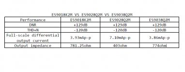
According to the chart, mono mode with ES9028Q2M would output 14.2mA P-P per channel. Still well within the capabilities of OPA1612. Just need to adjust the I/V feedback resistor and cap to get the right voltage swing, about 3v P-P, and retain the same RC time constant (if using the schematic I would offer up as one suggestion).
@terry22,
I did not compare them on the Katana. I'm not sure that Ian made the appropriate channels bi-directional as needed by the Katana. I'll check.
In the past I did compare Allo's original Isolator to Ian's IsolatorPi in the same setup with the same power source. I slightly preferred Allo's. The difference was not large. They were sufficiently close that I kept the IsolatorPi's I had in service and just used Allo's on my top-quality setups (RPi's modified with DC-DC converters removed and replaced by linear regulation).
Of course, Ian's soon-to-be available FIFOPi and Allo's Isolator 1.3 are different in function and would not compare apples to apples.
Greg in MIssissippi
Last edited:
- Home
- Source & Line
- PC Based
- Getting the best out of Allo.com's new Katana DAC...