Isolator is behaving differently in slave and master modes. This has something to do with the fact that on master mode isolator introduces 2 delays...one on BCK going to RPI and one on DATA coming from RPI (while on slave mode , all are delayed the same way so its canceled)
This is why we advise 24/192Khz as maximum if using isolator By resampling you are in fact lowering the delays and your music is playing correctly
Ok thank you for your answer.
Maybe you can add this to the documenation.
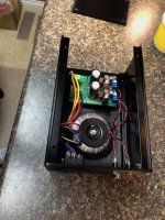
I'm familiar with these boards and tried them on my Katana. There is a bridge rectifier under each board and the pass transistors are bolted to the silver heatsinks. From what I can see the common mode chokes haven't been fitted.
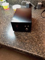
Don't know what that black metal thing is though...
J
Don't know what that black metal thing is though...
J
Why lose the trafos?
//
So as to allow more current output. The chokes shipped with those DIYINHK supplies are rated to 0.5A. Bypassing then allows, from memory, 1.5A.
@jonners & @jrocker, same filter choice as yours, preferred minimum phase slow roll-off during every iteration of the Katana development and for both SQ & THD+N output stages.
@TNT, @jrocker probably also saw the comments in post #196 where I related the assessment of my 'audio friend':
"The DAC board is powered by a DIYINHK LT3042 regulator with a series pass transistor in a low noise configuration according to the regulator chip data sheet, see: 0.8uV Ultralow noise DAC power supply regulator 3.3/5/7V 1.5A*x2 - DIYINHK. The CMC choke on the board has been bypassed - it sounds better without it."
He also bypassed the CMC choke on the same supply for the microprocessor board, saying:
"Likewise, the CMC choke on the board has been bypassed - it too sounded better without it."
2 very nice Katana packaged implementations in posts #245 by @terry22 & #262 by @jrocker (dual 5V power supplies only), along with @bvlabs full Katana setup in post #3119 of the main Allo thread New FIFO buffer for RPI/SBCs and a Boss setup in post @3127, along with a custom RPi->HAT power injection interface board in #3125 and details on adding a u.fl jack for WiFi external antenna to an RPi 3 in post #3133.
Great work all! AND @bvlabs, please make that interface board available via a GB!
AND I'm a bit like @John Luckins responding to @jrocker's boxed power supply... "Don't know what that black metal thing is though...".
There's also been some interesting discussion on using film cap banks on the +-15V rails over on the main Allo thread. My thoughts... I think the film cap banks are a good idea that should provide positive results in all cases if implemented well... good caps, soldered well, short leads to the Katana. I DO think the level of improvement will vary based on the quality of both the caps and of the +-15V supplies and how short of a connection each has to the Katana connection points. ANOTHER thing to consider is where you connect both the +-15V power and the film cap banks. Although I didn't go back and find the references, I do remember that some have either connected either the +-15V supplies and/or the cap banks to the leads of the larger cap on top of the microprocessor board. THIS cap is connected to the +-14V that goes directly into the opamp circuitry and is after the +-14V LDO regulators on the microprocessor board. Connecting here bypasses those regulators. Is that a good thing or bad thing? My take is that as a place to connect the cap bank, that is a good thing and likely one of the best places to connect them to get the maximum benefit... just make sure to find a good ground point for the center-tap connection. As for a place to feed the +-15V from a separate supply, first, I've checked with Allo and the opamp circuits will function quite nicely on +-15V instead of +-14V, so at least it is a safe connection point. Second, feeding the Sparkos opamps +-15V instead of the stock Katana +-14V is likely a bit better thing. Third, whether bypassing the Katana +-14V LDO regulators is a good thing again depends on the quality of both the regulators you use in your +-15V supply and those on the microprocessor board, which I haven't tracked down yet, but appear to be U4 & U5. My gut-feel is that if you use really good regulators AND can place them very close to the Katana if not right on top of it, then you are likely better off bypassing those LDO regulators. By really good, I mean regulators at the level of the Sparkos, Belleson, Dexa UWB-2, Superregs, and Salas, among others. IF you are using 'lesser' regulators, standard 317/337 types or similar, then going through the Katana LDO regulators will likely be better. Worth some experimentation someday!
Looking forward to further reports on Katana implementations and experimentation!
Greg in Mississippi
ANOTHER thing to consider is where you connect both the +-15V power and the film cap banks. Although I didn't go back and find the references, I do remember that some have either connected either the +-15V supplies and/or the cap banks to the leads of the larger cap on top of the microprocessor board.
I now have my +-15V "Studer 900" supplies connected as above, plus 50uF of film caps across each rail (more film caps on order). I'm hearing a smoother, more liquid and natural sound. It has the added advantage for me that I can now power up all the Katana supplies together, and my +-15V supply no longer has trouble connecting.
@Jonathan P, on the Katana balanced outputs, my advice is to go ahead and try them. The circuitry and filtering used by Allo is very similar to that used by 90%-95% of the commercial ESS-chip-based DACs out in the world. Once Allo said that the balanced outputs filtering was equivalent to the single-ended outputs, I have no reservations suggesting people try them. I understand what @Markw4 was discussing around balanced output circuitry and while it has merit, I worry that too much theoretical discussions outside of what can be done with the stock Allo Katana hardware with only minor mods (like bypassing the USB3 for 5V power to the Microprocessor board or all of the powering-options that everyone explored, including @Markw4's cap bank) will only muddy the waters and confuse many. Perhaps it is time for an 'Allo Katana SERIOUS Mods' or 'Improvements for the Katana 2.0' thread?
BTW, if you look closely at the SMD components right at each set of balanced output pads, you'll see the passive filtering components there.
@Jonathan P, please let us know how the balanced outputs work for you if you try them. Doing that is also on my list of things to try, but see my comments above.
Greg in Mississippi
@Greg, @Markw4, @csdgames, Long time no talk... I've been away, skiing in the Great Yellow Stone National Park area!
So I finally tried the Katana balanced output with neutrik XLR connectors and mogami XLR cables I built following this guide:
how-to-make-a-50-high-end-xlr-interconnect
Comparing the result with a 200$ set of Mackenzie RCA cables, it sounds really similar to me but I'll report back soon once I get my friend's feedback. He has better ears and much more Hi-Fi audio listening experience than I do. Next step could be to compare with re-balancing Katana's unbalanced output with Markw4's suggested circuit.
@Markw4,
How would you connect the balancing circuitry to the Katana?
Do you think it's possible to do so by keeping the RCA connectors in place without affecting the sound quality?
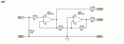
What do you think about this NE5532 implementation (PCB version)?
Circuit
PCB
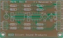
Jonathan, also, with all due respect, based on some of your questions and comments, I can tell you don't have much experience or knowledge in electronics builds.....
There's nothing wrong with that, we all started there. BUT I would strongly suggest that a Twisted Pear Placid HD Bipolar is NOT an appropriate kit for someone with that level of knowledge. ....
@Greg, .... I must admit that You unmasked me on the "don't have much experience or knowledge in electronics builds”.
I used my standard Deans high-current plugs for the connectors (these are from my model aviation hobby) AND Audience 18g hookup wire for the wire. On the Microprocessor board, I soldered the - to the - lead of the supercap and the + to the + side of the nearby ceramic cap. An alternative for the - lead is to solder to the metal outer case of the USB-C connector... that is what I did on the Boss 1.2.
[/QUOTE]
@Greg, Based on your text and photos, it’s still not 100% clear to me where you soldered the red wire to bypass the usb connector on the MC board…. So following my “Better safe than sorry” attitude… I have to ask if you would be kind enough to help me make this aweful doubt disappear from my mind?
Also, regarding PSU barrel and Katana J31 connectors bypass, soldering wires straight to Katana’s J31, you mentioned that it was ‘Not a huge improvement, but much more than a subtle one and well worthwhile!’.
Would you say it’s worth cutting a 50$ ifi iPower cord for it?
Would that be better than Grounding the iPower or could/should it still be grounded?
@Jonathan P
I think it would be fine to keep the Katana RCA connectors and just plug the balancing circuit input into that. However, I would probably use a newer opamp than 5532, maybe LME49720 or OPA1612. Also, it will help if they are powered off the +-15v power that is filtered with film caps. In addition they should have proper bypassing with 10uf tantalum and .1uf X7R ceramic caps right at the power pins, from there to ground. If you know how you should construct the circuit with a ground plane. If the PCB you showed has a substantial ground plane then that is probably okay, otherwise a way to do it for another circuit that could be used to get an idea how it might be done is described the documentation package at the following link: Dropbox - Output Stage Instructions.zip
I think it would be fine to keep the Katana RCA connectors and just plug the balancing circuit input into that. However, I would probably use a newer opamp than 5532, maybe LME49720 or OPA1612. Also, it will help if they are powered off the +-15v power that is filtered with film caps. In addition they should have proper bypassing with 10uf tantalum and .1uf X7R ceramic caps right at the power pins, from there to ground. If you know how you should construct the circuit with a ground plane. If the PCB you showed has a substantial ground plane then that is probably okay, otherwise a way to do it for another circuit that could be used to get an idea how it might be done is described the documentation package at the following link: Dropbox - Output Stage Instructions.zip
Last edited:
@Greg, Based on your text and photos, it’s still not 100% clear to me where you soldered the red wire to bypass the usb connector on the MC board…. So following my “Better safe than sorry” attitude… I have to ask if you would be kind enough to help me make this aweful doubt disappear from my mind?
I have mine connected as shown in this post of Greg's: https://www.diyaudio.com/forums/pc-based/329911-getting-allo-coms-katana-dac-20.html#post5666270
1-
2-
- unbalanced sounds a little more detailed (finer grain)
- balanced sounds significantly more dynamic, with much more "éclat" (or glow?), especially for instruments like piano
I'll let you guys know once I get the chance to try better XLR cables and/or try to re-balance the unbalanced output with @Markw4's proposed balancing circuit.
3- Now that I have a working 4 PSU setup, it's starting to sound pretty good. In fact, the only major thing that my friend and I find that is lacking is some "richness" in voice and piano... Like if there could/should be more harmonics, especially in the low end....
If you understand what I mean, could you guys advise on what mod(s) could help best in this area? I'm not sure if I should focus on mods like bypassing Common Mode Chokes and Connectors, adding Film Caps on +-15V rails, get better 5V PSUs, investigate/fix grounding issues, etc.
Here's a summary of my current setup:
- Isolator : allo basic PSU connected through usb connector
- MC : ifi iPower connected through usb connector
- DAC : ifi iPower connected through J31 connector
- SQ board : Placid HD BP 2.1 connected through J27 on MC board
4- Regarding grounding... Do you guys ground the Placid HD BP? Not sure it's an issue and forgive my ignorance but I wonder how the output GND (pin 2) can be guaranteed to be stable at 0V otherwise... In my case, with load connected, I can see the voltage fluctuate from -0.02V to 0.01V between the "+ GND -" outputs.
5- Regarding Placid HD BP shunt current threshold, did you guys agreed on a value? I think I read something around 300mA?
Thanks!
To my ears, the "Apodizing Fast Roll-off Filter" sounds better compared to the "minimum phase slow roll-off Filter". Instruments like bells and cymbals can be heard longer before they fade out. I’m using the Sound Quality output stage.I'm interested to know what filters and upsampling people are using.
I'm on the SQ output stage, no upsampling and minimum phase slow roll-off filter.
2-
As promised, I did more listening with my audiophile friend and compared balanced vs unbalanced outputs. Obviously, it's hard to compare since cable quality differs greatly BUT we noticed the following distinctive characteristics comparing the DIY XLR cable with both 200$ Mackenzie and 1000$++ Audience AU24se RCA cables:...So I finally tried the Katana balanced output with neutrik XLR connectors and mogami XLR cables I built following this guide:
how-to-make-a-50-high-end-xlr-interconnect
- unbalanced sounds a little more detailed (finer grain)
- balanced sounds significantly more dynamic, with much more "éclat" (or glow?), especially for instruments like piano
I'll let you guys know once I get the chance to try better XLR cables and/or try to re-balance the unbalanced output with @Markw4's proposed balancing circuit.
3- Now that I have a working 4 PSU setup, it's starting to sound pretty good. In fact, the only major thing that my friend and I find that is lacking is some "richness" in voice and piano... Like if there could/should be more harmonics, especially in the low end....
If you understand what I mean, could you guys advise on what mod(s) could help best in this area? I'm not sure if I should focus on mods like bypassing Common Mode Chokes and Connectors, adding Film Caps on +-15V rails, get better 5V PSUs, investigate/fix grounding issues, etc.
Here's a summary of my current setup:
- Isolator : allo basic PSU connected through usb connector
- MC : ifi iPower connected through usb connector
- DAC : ifi iPower connected through J31 connector
- SQ board : Placid HD BP 2.1 connected through J27 on MC board
4- Regarding grounding... Do you guys ground the Placid HD BP? Not sure it's an issue and forgive my ignorance but I wonder how the output GND (pin 2) can be guaranteed to be stable at 0V otherwise... In my case, with load connected, I can see the voltage fluctuate from -0.02V to 0.01V between the "+ GND -" outputs.
5- Regarding Placid HD BP shunt current threshold, did you guys agreed on a value? I think I read something around 300mA?
Thanks!
- Home
- Source & Line
- PC Based
- Getting the best out of Allo.com's new Katana DAC...
