Hey all,
We have worked out how to retrofit 2 channel embedded systems with 8 channels of audio. The end result is a very compact sub $100 networkable audio machine !
Greate for crossovers, multitrack recording, surround sound or anything else which takes your fancy")
Check the back story on this project here :
https://forum.xda-developers.com/ra...s/love-making-impossible-happen-8-ch-t3541058
If anyone has ideas on how to push this audio story out through media, I would love to hear about it.
Check out the kickstarter page :
https://www.kickstarter.com/projects/1250664710/audio-injector-octo-surround-sound-for-the-raspber
Matt
We have worked out how to retrofit 2 channel embedded systems with 8 channels of audio. The end result is a very compact sub $100 networkable audio machine !
Greate for crossovers, multitrack recording, surround sound or anything else which takes your fancy
Check the back story on this project here :
https://forum.xda-developers.com/ra...s/love-making-impossible-happen-8-ch-t3541058
If anyone has ideas on how to push this audio story out through media, I would love to hear about it.
Check out the kickstarter page :
https://www.kickstarter.com/projects/1250664710/audio-injector-octo-surround-sound-for-the-raspber
Matt
This offers analog input and output capabilities for the Pi platform that are simply not available anywhere else at this time. I'm very interested in testing these boards and I have signed up as part of the kickstarter project.
These could really be a boon for multichannel DSP crossovers using the Pi platform.
These could really be a boon for multichannel DSP crossovers using the Pi platform.
TEST RESULTS: Octo soundcard for the Raspberry Pi (6-input, 8-output)
INTRO:
I received today in the mail a nice pair of the Flatmax Studios Audio Injector "Octo" soundcard for the Raspberry Pi. This offers by far the greatest number of audio inputs (six) and outputs (eight) for the Pi of any non-USB sound hardware that I am aware of, and can run at a sampling rate of up to 96kHz. The board is built around the CS42448 codec from Cirrus, a midlevel audio codec for home theater and automotive use that integrates ADCs and DACs onboard. The hardware is interfaced with the Pi via its GPIO pins (it's a "HAT") and two ribbon cables lead off board to the I/O jacks. I decided to do a few tests to see what to expect from this new and very interesting option for audio on the Raspberry Pi. I purchased the versions with RCA jacks, since this seemed to be best for my needs. This is the version tested here.
SETUP:
I assembled the HAT onto a Pi 2 and connected the ribbon cables. These are not super long, but just long enough to locate the RCA connector boards a few centimeters away from the Pi board itself. I then followed the instructions on the Flatmax Studio web page to download a deb file and then use it to perform the setup. This went flawlessly and after the required reboot I could immediately see that the new octo card was now the only sound platform available (the onboard audio of the Pi, including HDMI audio, is disabled during the setup process). With that done it was time for some testing.
GETTING STARTED:
It's not generally possible (or at least I do not have the capability) to do a loopback test of a Raspberry Pi based soundcard because of the lack of testing software for the Raspbian platform. Instead I used an M-Audio ProFire610 audio interface connected to my desktop to send/receive audio to/from the octo HAT. On the Pi I ran ecasound to accept audio from the HAT's input and send it to the HAT's output. Between the two I ran two RCA cables, forming a single-channel loop thru the octo HAT. On my desktop computer I used ARTA (for frequency response and distortion vs frequency) and REW5.0 (run in spectrum analyzer mode) to make measurements on the system. All measurements were done in single channel mode.
At first I had some trouble getting any audio to pass through the system. I tried various software parameters on the Pi and via ecasound to troubleshoot. I also checked the levels for the DACs and ADCs of the octo HAT using alsamixer. After a while I started switching which physical jacks I was using for input and output. It was then that I discovered that there seems to be a mis-wiring on either the RCA input or RCA output board. There are 6 (input) and 8 (output) jacks but there is no numbering or other identification. I simply used the red jack on the end that I assumed was the "first" channel for each. But I could only get audio working when I had the RCA cables connected to red on one and white on the other. I assume that between the HAT board and the RCA jacks there is a mistake in the connection such that this channel is reversed. I did not check all the channels to see if the entire input or output block is reversed, red-to-white, or if just this one pair of channels had been reversed, but it is something that needs to be investigated.
MEASUREMENTS:
Once I got audio going I could proceed to some audio measurements. I found some interesting results, some good and some not so good.
THE GOOD...
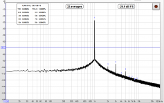
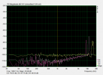
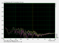
On the good side of the coin, at 44.1k and 48kHz the distortion levels are relatively decent. At full level and 1kHz the THD is around -80dB or 0.01% and remains relatively the same across the audio band. 2nd order dominates, with 3rd order 8-10dB lower. The -3dB point at low frequencies is 6Hz and the response is down by 0.5dB at 20kHz.
THE BAD...
I measured distortion levels that were quite a bit higher when I ran the board at 96kHz. The THD was about -66dB at 1kHz and actually rose about 6dB above that below about 500Hz. Above 1kHz the THD levels were flat or trending lower (better) by another 6dB. THD of -66dB is about 0.05% which is not all that good for a DAC at max output level. I was concerned about worse performance at 96kHz after reading the datasheet for the codec, and this is more or less confirming what I read. The board is best used at 44.1 or 48kHz. That's not the end of the world - I run some of my R-Pi based DSP systems at 48kHz all the time. But given the 15-20dB worse THD levels compared to the lower rates I would not recommend using the 96kHz rate on this board.
THE UGLY...
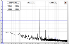
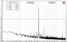
My biggest concern about this board when I saw it on paper back a few months ago was the potential for it to be relatively noisy. The board is sitting right on top of a small computer, which is a great noise generator and the number provided by the MFG for best case scenario is, frankly, "middle of the road". So as you might imagine I was eager to measure it. To do this I used REW to record the audio spectrum when the board was fed a 1kHz sine wave. REW has the ability to measure THD and THD+N when operated in spectrum mode, and it gives the values in percent. To get the noise floor I subtracted the THD value from the THD+N value and converted the result to decibels using an online calculator. The result was disappointing. The noise floor is only 66dB down running at 44.1kHz. That's pretty bad. This improves to 70dB down running at 48kHz, which is a little better but still not good. Worst of all was the 96kHz reading, where the noise floor was just barely better than 40dB down. That's atrocious. Just another reason to avoid using this board at 96kHz.
I have attached screen shots of some of my measurements if you want to give it a look.
PUTTING THINGS INTO PERSPECTIVE:
How do these numbers compare to other audio interfaces? Let's start with an on-board ALC892 codec on a small mini-ITX system of mine. It's not high end, but 1kHz THD comes in somewhat lower at 0.004% (-87dB). The noise floor is also not great, at 76dB below full output level. This is your average computer 7.1+2 soundcard. What about a multichannel interface that can be used with the Raspberry Pi? One I recently measured is the Asus Xonar U7, a 7.1 system that transfers data to/from the Pi via USB. I measured it connected to the exact same R-Pi system, and found THD at 1kHz of 0.006% and a noise floor coming in still lower at -81dB. I also recently measured a pro audio interface, the Behringer FCA610, also using the M-Audio (not doing a direct loopback on the FAC610). The 1kHz distortion measured 0.004% (-87dB) and the noise was 84dB down. But when I measured this by connecting the FCA610 to my desktop and doing a direct loopback measurement on it, 1kHz THD was slightly higher at 0.0058 (-84dB) while the noise floor fell to under 100dB below full scale. This would seem to indicate that my M-Audio audio interface has a noise floor between -85dB and -90dB itself. Since I did only single channel measurements the M-Audio was always part of the measurement chain. Looking back at some earlier stereo DAC measurements made withe the M-Audio I have recorded a noise floor of 91dB below full scale before, meaning the M-Audio must have at least that low of a noise floor, or slightly lower.
Of the three multichannel DAC options (octo HAT, Asus Xonar U7, and Behringer FCA610) the performance scales along with the price point. The Behringer comes in at almost twice the cost of the octo HAT, with the Asus in the middle. Only the HAT does not need its own power supply, since it gets it from the Pi.
CONCLUSIONS:
Despite having a bit of a high noise floor, I can say that the octo HAT still brings some very good performance to the table as long as you use it at 44.1kHz or 48kHz sampling rates. For casual use it would make a great 8-out crossover for DIY loudspeakers or surround sound. Just make sure to figure out which RCA output or input is which to keep your audio going to the right place.
It's possible that the noise levels could be reduce by moving the HAT away from the Pi board using a 40-pin ribbon cable between the GPIO pins of the PI and the HAT board. The HAT could then be put into some shielding, with the I/O boards mounted in the side. It's something that could be explored... unfortunately I do not have such a cable at my disposal. Another source of noise could be the power coming from the Pi, and some filtering could be added or lower noise regulators used on the HAT.
With the success of the octo HAT and the previous audio injector 2-in, 2-out HAT, the Flatmax team might turn their attention on how to raise the audio quality bar with their next project, perhaps with a better codec or cleaner power. I am sure that there are plenty of eager DIYers looking for a high quality R-Pi sound option and that this demand is world-wide. It's food for thought.
INTRO:
I received today in the mail a nice pair of the Flatmax Studios Audio Injector "Octo" soundcard for the Raspberry Pi. This offers by far the greatest number of audio inputs (six) and outputs (eight) for the Pi of any non-USB sound hardware that I am aware of, and can run at a sampling rate of up to 96kHz. The board is built around the CS42448 codec from Cirrus, a midlevel audio codec for home theater and automotive use that integrates ADCs and DACs onboard. The hardware is interfaced with the Pi via its GPIO pins (it's a "HAT") and two ribbon cables lead off board to the I/O jacks. I decided to do a few tests to see what to expect from this new and very interesting option for audio on the Raspberry Pi. I purchased the versions with RCA jacks, since this seemed to be best for my needs. This is the version tested here.
SETUP:
I assembled the HAT onto a Pi 2 and connected the ribbon cables. These are not super long, but just long enough to locate the RCA connector boards a few centimeters away from the Pi board itself. I then followed the instructions on the Flatmax Studio web page to download a deb file and then use it to perform the setup. This went flawlessly and after the required reboot I could immediately see that the new octo card was now the only sound platform available (the onboard audio of the Pi, including HDMI audio, is disabled during the setup process). With that done it was time for some testing.
GETTING STARTED:
It's not generally possible (or at least I do not have the capability) to do a loopback test of a Raspberry Pi based soundcard because of the lack of testing software for the Raspbian platform. Instead I used an M-Audio ProFire610 audio interface connected to my desktop to send/receive audio to/from the octo HAT. On the Pi I ran ecasound to accept audio from the HAT's input and send it to the HAT's output. Between the two I ran two RCA cables, forming a single-channel loop thru the octo HAT. On my desktop computer I used ARTA (for frequency response and distortion vs frequency) and REW5.0 (run in spectrum analyzer mode) to make measurements on the system. All measurements were done in single channel mode.
At first I had some trouble getting any audio to pass through the system. I tried various software parameters on the Pi and via ecasound to troubleshoot. I also checked the levels for the DACs and ADCs of the octo HAT using alsamixer. After a while I started switching which physical jacks I was using for input and output. It was then that I discovered that there seems to be a mis-wiring on either the RCA input or RCA output board. There are 6 (input) and 8 (output) jacks but there is no numbering or other identification. I simply used the red jack on the end that I assumed was the "first" channel for each. But I could only get audio working when I had the RCA cables connected to red on one and white on the other. I assume that between the HAT board and the RCA jacks there is a mistake in the connection such that this channel is reversed. I did not check all the channels to see if the entire input or output block is reversed, red-to-white, or if just this one pair of channels had been reversed, but it is something that needs to be investigated.
MEASUREMENTS:
Once I got audio going I could proceed to some audio measurements. I found some interesting results, some good and some not so good.
THE GOOD...
On the good side of the coin, at 44.1k and 48kHz the distortion levels are relatively decent. At full level and 1kHz the THD is around -80dB or 0.01% and remains relatively the same across the audio band. 2nd order dominates, with 3rd order 8-10dB lower. The -3dB point at low frequencies is 6Hz and the response is down by 0.5dB at 20kHz.
THE BAD...
I measured distortion levels that were quite a bit higher when I ran the board at 96kHz. The THD was about -66dB at 1kHz and actually rose about 6dB above that below about 500Hz. Above 1kHz the THD levels were flat or trending lower (better) by another 6dB. THD of -66dB is about 0.05% which is not all that good for a DAC at max output level. I was concerned about worse performance at 96kHz after reading the datasheet for the codec, and this is more or less confirming what I read. The board is best used at 44.1 or 48kHz. That's not the end of the world - I run some of my R-Pi based DSP systems at 48kHz all the time. But given the 15-20dB worse THD levels compared to the lower rates I would not recommend using the 96kHz rate on this board.
THE UGLY...
My biggest concern about this board when I saw it on paper back a few months ago was the potential for it to be relatively noisy. The board is sitting right on top of a small computer, which is a great noise generator and the number provided by the MFG for best case scenario is, frankly, "middle of the road". So as you might imagine I was eager to measure it. To do this I used REW to record the audio spectrum when the board was fed a 1kHz sine wave. REW has the ability to measure THD and THD+N when operated in spectrum mode, and it gives the values in percent. To get the noise floor I subtracted the THD value from the THD+N value and converted the result to decibels using an online calculator. The result was disappointing. The noise floor is only 66dB down running at 44.1kHz. That's pretty bad. This improves to 70dB down running at 48kHz, which is a little better but still not good. Worst of all was the 96kHz reading, where the noise floor was just barely better than 40dB down. That's atrocious. Just another reason to avoid using this board at 96kHz.
I have attached screen shots of some of my measurements if you want to give it a look.
PUTTING THINGS INTO PERSPECTIVE:
How do these numbers compare to other audio interfaces? Let's start with an on-board ALC892 codec on a small mini-ITX system of mine. It's not high end, but 1kHz THD comes in somewhat lower at 0.004% (-87dB). The noise floor is also not great, at 76dB below full output level. This is your average computer 7.1+2 soundcard. What about a multichannel interface that can be used with the Raspberry Pi? One I recently measured is the Asus Xonar U7, a 7.1 system that transfers data to/from the Pi via USB. I measured it connected to the exact same R-Pi system, and found THD at 1kHz of 0.006% and a noise floor coming in still lower at -81dB. I also recently measured a pro audio interface, the Behringer FCA610, also using the M-Audio (not doing a direct loopback on the FAC610). The 1kHz distortion measured 0.004% (-87dB) and the noise was 84dB down. But when I measured this by connecting the FCA610 to my desktop and doing a direct loopback measurement on it, 1kHz THD was slightly higher at 0.0058 (-84dB) while the noise floor fell to under 100dB below full scale. This would seem to indicate that my M-Audio audio interface has a noise floor between -85dB and -90dB itself. Since I did only single channel measurements the M-Audio was always part of the measurement chain. Looking back at some earlier stereo DAC measurements made withe the M-Audio I have recorded a noise floor of 91dB below full scale before, meaning the M-Audio must have at least that low of a noise floor, or slightly lower.
Of the three multichannel DAC options (octo HAT, Asus Xonar U7, and Behringer FCA610) the performance scales along with the price point. The Behringer comes in at almost twice the cost of the octo HAT, with the Asus in the middle. Only the HAT does not need its own power supply, since it gets it from the Pi.
CONCLUSIONS:
Despite having a bit of a high noise floor, I can say that the octo HAT still brings some very good performance to the table as long as you use it at 44.1kHz or 48kHz sampling rates. For casual use it would make a great 8-out crossover for DIY loudspeakers or surround sound. Just make sure to figure out which RCA output or input is which to keep your audio going to the right place.
It's possible that the noise levels could be reduce by moving the HAT away from the Pi board using a 40-pin ribbon cable between the GPIO pins of the PI and the HAT board. The HAT could then be put into some shielding, with the I/O boards mounted in the side. It's something that could be explored... unfortunately I do not have such a cable at my disposal. Another source of noise could be the power coming from the Pi, and some filtering could be added or lower noise regulators used on the HAT.
With the success of the octo HAT and the previous audio injector 2-in, 2-out HAT, the Flatmax team might turn their attention on how to raise the audio quality bar with their next project, perhaps with a better codec or cleaner power. I am sure that there are plenty of eager DIYers looking for a high quality R-Pi sound option and that this demand is world-wide. It's food for thought.
Attachments
-
 R-Pi octo soundcard 44.1kHz 32bit 1kHz spectrum and THD-N.PNG77.9 KB · Views: 946
 -
 R-Pi octo soundcard 48kHz 32bit 1kHz spectrum and THD-N.PNG77.8 KB · Views: 985
 -
 R-Pi octo soundcard 96kHz 32bit 1kHz spectrum and THD-N.PNG69.3 KB · Views: 932
 -
 44.1kHz FR and distortion.PNG55 KB · Views: 929
 -
 48kHz FR and distortion.PNG53.8 KB · Views: 928
 -
 96kHz FR and distortion.PNG56 KB · Views: 111
Thanks for the test. I also received my Octo and brand new RPi 3B today. I set it up to do live processing using Reaper for Linux. The developer has an ARM version which worked fine on the first try.
I built a 4 way crossover by creating four stereo output busses, inserting parametric EQ, filtering and delays on each bus, and sending one live input to all 4 busses. The CPU load in this configuration is in the 25% range and I did not get any audio glitches or dropouts.
I will run some analysis on mine later, but I have to say that using headphones to listen to each output I did not hear any hiss, but the audio itself was a bit dull sounding.
I used my cell phone as a quick source for testing and a mid range quality amp to drive the headphones, so I will reserve my final judgement as to sound quality until later.
Which version of RPi do yo use and what type of power supply? Is it possible that the power supply is introducing artifacts and a filtered supply would result in better numbers?
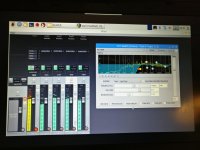
Attached is a screenshot of my laptop running a VNC session with the RPi.
I built a 4 way crossover by creating four stereo output busses, inserting parametric EQ, filtering and delays on each bus, and sending one live input to all 4 busses. The CPU load in this configuration is in the 25% range and I did not get any audio glitches or dropouts.
I will run some analysis on mine later, but I have to say that using headphones to listen to each output I did not hear any hiss, but the audio itself was a bit dull sounding.
I used my cell phone as a quick source for testing and a mid range quality amp to drive the headphones, so I will reserve my final judgement as to sound quality until later.
Which version of RPi do yo use and what type of power supply? Is it possible that the power supply is introducing artifacts and a filtered supply would result in better numbers?
Attached is a screenshot of my laptop running a VNC session with the RPi.
Attachments
I don't think the power supply contributed to the problem, although I suppose I would need a scope to know for sure. It's a 2.5A 5.25V supply sold by MCM for the Pi. The board should have PS filtering via the regulators and associated components.
I used a pretty recent distro of Raspbian, with the Pixel desktop.
I look forward to your evaluation so that I can compare it to my own.
-Charlie
I used a pretty recent distro of Raspbian, with the Pixel desktop.
I look forward to your evaluation so that I can compare it to my own.
-Charlie
Hey Charlie,
I have now done a loopback test on my audio injector octo card and the results I see are very different from your results.
I see the following :
SNR of 90 dB
1st harmonic at -70 dB.
Check them out here :
sound quality - AudioInjector Forums
Is it possible for you to try a loopback test ?
Perhaps one without the RCA connectors (pin to pin ADC to DAC connections from the headers) and one with the RCA connector (RCA to RCA) ?
thanks
Matt
Last edited:
I don't think the power supply contributed to the problem, although I suppose I would need a scope to know for sure. It's a 2.5A 5.25V supply sold by MCM for the Pi. The board should have PS filtering via the regulators and associated components.
I used a pretty recent distro of Raspbian, with the Pixel desktop.
I look forward to your evaluation so that I can compare it to my own.
-Charlie
HI Charlie,
I have now completed a nice loopback test on the AudioInjector octo. I find much better results @ 96 kHz :
Dynamic range of arguably more then 90 dB.
1st harmonic down -70 dB with the RCA connectors.
1st harmonic < -90 dB (in the noise floor) when connecting DAC pin to ADC pin using the headers on the board.
You can read more about my test here :
sound quality - AudioInjector Forums
Hey there,
I find different results when I do a loopback on the Octo at 96 kHz. More like 90 dB SNR and -70 dB 1st harmonic distortion with RCAs and > -90 dB 1st harmonic distortion when connecting ADCs directly to DACs using the header.
You can see the full results on the Audio Injector forum.
thanks
Matt
I find different results when I do a loopback on the Octo at 96 kHz. More like 90 dB SNR and -70 dB 1st harmonic distortion with RCAs and > -90 dB 1st harmonic distortion when connecting ADCs directly to DACs using the header.
You can see the full results on the Audio Injector forum.
thanks
Matt
Hmmm, that's quite a bit better than I measured. I explained my measurement gear in the GETTING STARTED section of post #4 of this thread.
A pin-to-pin measurement is totally irrelevant to use of the board for audio... it's better to see how it performs when it is connected to other equipment, like it will be in "real world" use.
I would very much like to see measurements done by you or others using external equipment, e.g. a pass-thru measurement where you send a signal from the external equipment to the octo board, pass it thru internally, and return the octo board output to the external equipment. This is what I did, so it would be more of an apples-to-apples comparison and corresponds more closely to what you would see in real life (the octo board connected to external equipment).
The setup I used for the octo board is one that I have used for many measurements in the past of DACs and other equipment. It's certainly possible that there was some kind of problem, however, I haven't experienced any problems before or since doing the octo measurements. I still have the boards, so it would be possible to repeat my measurements.
Last edited:
Hi Charlie,
I have now repeated my experiment by using my PC as the source/sink with it's on board sound card. There is more noise, however the results are still almost the same.
You can see my post here :
Characterisation of the Octo - noise and harmonic distortion tests - AudioInjector Forums
I have moved my original post to its own thread here :
Characterisation of the Octo - noise and harmonic distortion tests - AudioInjector Forums
thanks
Matt
"Dynamic Range" is more or less a meaningless metric here.
Noise floor is very important, especially when the maximum output is barely 1Vrms (at least I recall that was approximately the maximum voltage output from the RCA version of the octo board that I purchased). I didn't see a noise floor measurement in your posts. I am happy to walk you through an HD and noise measurement using REW from your PC if you drop me a PM.
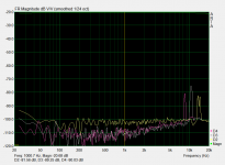
IMHO, -70dB 2nd order harmonic distortion is really not good at all for a DAC. The THD will be worse because I can clearly see the 3rd order distortion peak on your plot and it is not much lower than the 2nd order distortion peak. It's not the 3141 Hz peak that you annotate, it's the larger one at 3kHz.
While you seem to be able to get much better results right at the pins of the CS42448 that only shows that the additional circuitry (at the output and input) is adding noise and distortion, possibly because the ground of the octo board is contaminated by noise from its proximity to the Pi (or that is my guess at least) and also possibly the choice of capacitors in the audio signal path.
Noise floor is very important, especially when the maximum output is barely 1Vrms (at least I recall that was approximately the maximum voltage output from the RCA version of the octo board that I purchased). I didn't see a noise floor measurement in your posts. I am happy to walk you through an HD and noise measurement using REW from your PC if you drop me a PM.
IMHO, -70dB 2nd order harmonic distortion is really not good at all for a DAC. The THD will be worse because I can clearly see the 3rd order distortion peak on your plot and it is not much lower than the 2nd order distortion peak. It's not the 3141 Hz peak that you annotate, it's the larger one at 3kHz.
While you seem to be able to get much better results right at the pins of the CS42448 that only shows that the additional circuitry (at the output and input) is adding noise and distortion, possibly because the ground of the octo board is contaminated by noise from its proximity to the Pi (or that is my guess at least) and also possibly the choice of capacitors in the audio signal path.
I think the point about THD is like this ... Without DC blocking caps, there is very little harmonic distortion at all. With work on analogue buffers, the THD can be reduced dramatically.
People have the ability to access the DAC and ADC pins ... so for example if someone wants to interface an analogue synth @ very close to DC, they can - with very little nonlinearity ...
With nothing plugged into the system, the noise floor @ 96 kHz approaches that @ 48 kHz. Pin to pin loopback approaches great noise floor levels - and that is with the input noise floor superimposed onto the output noise floor ... consequently the output noise floor alone is better the quoted and same goes for the input noise floor alone.
If people want great quality output and input from one of these devices, then it is clear that it is possible with higher quality (instrumentation amplifier type) analogue buffers.
Matt
Are you saying that the board, as is (without either the RCA or balanced outputs) is what you are measuring when you use the term "pin-to-pin"? You are then measuring the "pin" at the header? Can you please clarify?
If that is the case, are you then suggesting that a better output buffering system could improve the performance, making the actual usable audio output close to what you can measure at "the pin"?
It could certainly be that the ribbon cable connector is the source of the noise pickup... Distortion would be from components, circuitry, etc.
Just a little note on measuring these types of systems ...
It really depends on your usage how to measure this thing - right ?
Consider that a pin to pin connection adds input and output noise floors ... which would mimic an output setup where the audio injector Octo is used to drive an amplifier or something similar ... in that case, the actual noise floor would be similar to what you would expect. Something like the following :
1] First noise introduced by the cs42448 codec's analogue output stage (some sort of opamp setup internal to the chip)
2] Second noise floor introduced by the amplifier or other equiment used in the chain.
That makes only two noise floors - input and output noise floors - similar to a pin to pin setup for measurement.
A different scenario includes noise from 4 systems - namely the concept of measuring the equipment through a second codec (ADC+DAC) :
1] measurement system's output buffer noise
2] Audio Injector Octo's input buffer noise
3] Audio Injector Octo's output buffer noise
4] measurement system's input buffer nosie
That is a lot of injected noise. If there is a ground loop introduced or anything else which is particular to either system or the combination of systems, then that noise is in the mix. So that is a rather significant complication on the measurement matter.
Matt
Uses for RPI and Octo
Charlie,
I have been away from the forum a long time. I finally got to putting together my Octo onto a RPI4 I got for Christmas. After some canoodling I got it to work and record some audio into Audacity, Ardour and Reaper using the NOOBS Raspbian OS.
I only had a little time with it but it was a thrill to get it to work.
What did you end up doing with yours?
- Status
- This old topic is closed. If you want to reopen this topic, contact a moderator using the "Report Post" button.
- Home
- Source & Line
- PC Based
- Introducing the Audio Injector