That is correct. A Gaussian follows the equation of the form "exp(-x^2)". Us of any power other than 2 is not a Gaussian. That is why I am so careful to label an equation of the form "exp(-|x|^N)" (N not equal to 2) as "Gaussian-like".Today I have no time to scan the entire thread. I vaguely remember that Berchin wrote that one must remain cautious about the wording. I vaguely remember Berchin wrote that "Gaussian" means nothing else than applying a Gauss curve as FIR ...
The Bessel is an IIR approximation of the Gaussian. You have the luxury of huge amounts of processing power at your disposal in your FFT-based implementation. That is not true in all cases, and an 8th-order digital IIR filter requires far less processing than, for example, a 256th-order (or even higher, at low cutoff frequencies) FIR.I have to admit that I have yet to come to terms with the motivation behind all these filter types! For example, the Bessel which you mention appears to be notable because of its constant group delay across the pass band (thanks Wikipedia!). Presumably, though, this is not a factor in a linear phase implementation..?
That is certaily a viable design procedure, but it is akin to shooting in the dark. The various filter "flavors" are each optimal in some sense, so if what they optimize happens to be important to you, then you can go right to the answer without guessing.Yes, it's the motivation behind the filter 'brands' that I'm not sure of. As far as I can tell, it is possible to 'dial in' a desired frequency response, and suck-it-and-see what you get in terms of the impulse response ringing. No real maths involved. If that doesn't meet your various criteria, you can then massage the frequency response iteratively until it does. And give up if it doesn't.
Because it's nice to actually understand the fundamentals behind what we are doing, rather than simply iterating until we (hopefully) find something that works.But in short, if we're designing a digital crossover filter, why do we need the maths and the filter 'brands'?
Consider a crossover demanding the tweeter to exhibit an acoustic 2nd-order highpass with F-3db = 3400 Hz. Consider the unfiltered tweeter Bode plot, showing a natural highpass with F-3dB = 800 Hz. The highpass crossover will thus only provide some attenuation between 800 Hz and 3400 Hz. All frequencies below 800 Hz will reach the tweeter, mostly unattenuated. This is what your so-called 2nd-order highpass crossover delivers.Steph, you keep making that statement without justification. The adequacy of a 2nd order highpass is entirely dependent upon the circumstances in which it is used. There are certainly situations in which a 2nd order highpass is insufficient, but to say that this is true in most cases is simply an overstatement. There are many, many cases in which a 2nd order highpass works very well indeed. And, as I mentioned in an earlier post, if it does not then perhaps one is either crossing over at too low a frequency, or using a tweeter inappropriate for the job.
If you want your tweeter to sound ill, to exceded its Xmax at high listening volumes, and overheat, that's exactly what you need.
Can you please describe the cases in which an acoustic 2nd order highpass works well, for a tweeter?
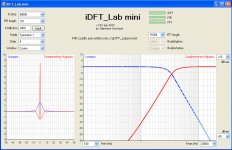
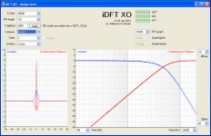
I just finished writing iDFT_Lab mini, dealing with linear phase complementary symmetric FIR crossovers.
"linear phase"
Both the lowpass and highpass exhibit a linear phase.
"complementary"
The sum of lowpass and highpass is equal to unity, both in amplitude and phase.
"symmetric"
When you view the amplitude plots with a log fequency scale, the lowpass slope and shape are the same flavour as the highpass slope and shape.
Now about the details.
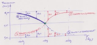
For the crossover to be symmetric, the lowpass attenuation curve must exhibit certain properties.
Let us draw the lowpass amplitude using linear Y (from zero to one - this is the transmission factor) and log X (10 Hz, 1 kHz, 10 kHz, etc ...).
The X midpoint is thus 1 kHz.
Say 1kHz is Fc, the crossover frequency.
We know that at Fc, the lowpass amplitude is 0.5.
See the attached .jpg sketch
0) Let us draw the (1 kHz, 0.5) point in green, the crossing point
1) Let us draw an arbitrary lowpass amplitude on the log frequency scale spanning from 100 Hz to Fc.
2) Because of the symmetry that we are targeting, the corresponding highpass amplitude from Fc to 10 kHz, also got defined.
3) Because of the lowpass/highpass complementarity, the corresponding lowpass amplitude from Fc to 10 kHz, also got defined (dy1 and dy2 in red).
4) Because of the lowpass/highpass complementarity, the corresponding highpass amplitude from 10 Hz to Fc, also got defined (dy1 and dy2 in blue).
Looking at the four curve segments that just got defined, we realize that there is a central symmetry, with the particular (1 kHz, 0.50) point acting as centre.
The DC to Fs/2 lowpass amplitude curve serves as input for the iDFT.
The iDFT output is the corresponding impulse response in time domain. This way we get the lowpass FIR coefficients.
Knowing the lowpass impulse response, we compute the complementary highpass impulse response, the usual way. This way we get the highpass FIR coefficients.
A particular straightforward way to get a Nth-order lowpass amplitude curve exhibiting the symmetry requirement is :
For i = 0 To N
F = FS * (i / N)
If F < Fcut Then GAIN(i) = 1 - (((F / Fcut) ^ order) / 2.0)
If F = Fcut Then GAIN(i) = 0.5
If F > Fcut Then GAIN(i) = (((Fcut / F) ^ order) / 2.0)
Next
There are many other ways to generate lowpass amplitude curves exhibiting the symmetry requirement. For a given filter slope (or order), one could try softening the lowpass edge close to Fc, in order to see the effect on the time domain preshoot and ringing. Currently I have no idea how to simply (mathematically) soften the lowpass edge close to Fc. And I would hate editing the iDFT input by hand. Any suggestion welcome.
Steph
"linear phase"
Both the lowpass and highpass exhibit a linear phase.
"complementary"
The sum of lowpass and highpass is equal to unity, both in amplitude and phase.
"symmetric"
When you view the amplitude plots with a log fequency scale, the lowpass slope and shape are the same flavour as the highpass slope and shape.
Now about the details.
For the crossover to be symmetric, the lowpass attenuation curve must exhibit certain properties.
Let us draw the lowpass amplitude using linear Y (from zero to one - this is the transmission factor) and log X (10 Hz, 1 kHz, 10 kHz, etc ...).
The X midpoint is thus 1 kHz.
Say 1kHz is Fc, the crossover frequency.
We know that at Fc, the lowpass amplitude is 0.5.
See the attached .jpg sketch
0) Let us draw the (1 kHz, 0.5) point in green, the crossing point
1) Let us draw an arbitrary lowpass amplitude on the log frequency scale spanning from 100 Hz to Fc.
2) Because of the symmetry that we are targeting, the corresponding highpass amplitude from Fc to 10 kHz, also got defined.
3) Because of the lowpass/highpass complementarity, the corresponding lowpass amplitude from Fc to 10 kHz, also got defined (dy1 and dy2 in red).
4) Because of the lowpass/highpass complementarity, the corresponding highpass amplitude from 10 Hz to Fc, also got defined (dy1 and dy2 in blue).
Looking at the four curve segments that just got defined, we realize that there is a central symmetry, with the particular (1 kHz, 0.50) point acting as centre.
The DC to Fs/2 lowpass amplitude curve serves as input for the iDFT.
The iDFT output is the corresponding impulse response in time domain. This way we get the lowpass FIR coefficients.
Knowing the lowpass impulse response, we compute the complementary highpass impulse response, the usual way. This way we get the highpass FIR coefficients.
A particular straightforward way to get a Nth-order lowpass amplitude curve exhibiting the symmetry requirement is :
For i = 0 To N
F = FS * (i / N)
If F < Fcut Then GAIN(i) = 1 - (((F / Fcut) ^ order) / 2.0)
If F = Fcut Then GAIN(i) = 0.5
If F > Fcut Then GAIN(i) = (((Fcut / F) ^ order) / 2.0)
Next
There are many other ways to generate lowpass amplitude curves exhibiting the symmetry requirement. For a given filter slope (or order), one could try softening the lowpass edge close to Fc, in order to see the effect on the time domain preshoot and ringing. Currently I have no idea how to simply (mathematically) soften the lowpass edge close to Fc. And I would hate editing the iDFT input by hand. Any suggestion welcome.
Steph
Attachments
Last edited:
A 2nd-order highpass will provide 25 dB attenuation between 3400 Hz and 800 Hz.Consider a crossover demanding the tweeter to exhibit an acoustic 2nd-order highpass with F-3db = 3400 Hz. Consider the unfiltered tweeter Bode plot, showing a natural highpass with F-3dB = 800 Hz. The highpass crossover will thus only provide some attenuation between 800 Hz and 3400 Hz.
At 800 Hz they will be attenuated by 25 dB.All frequencies below 800 Hz will reach the tweeter, mostly unattenuated. This is what your so-called 2nd-order highpass crossover delivers.
EDIT: I missed the "acoustic" in your statement, first time through, so you are correct about the level staying constant below 800 Hz. But by that time the signal has already been attenuated by 25 dB. That's a factor of 1/316 in power.
THIEL uses 1st order crossovers.If you want your tweeter to sound ill, to exceded its Xmax at high listening volumes, and overheat, that's exactly what you need.
Can you please describe the cases in which an acoustic 2nd order highpass works well, for a tweeter?
Furthermore, and I failed to make this point explicitly before, there are more crossovers than just tweeter crossovers. You said that 2nd-order highpass is inadequate in most situations. Well, when crossing over from a subwoofer to a full-range speaker, a common situation, 2nd-order highpass is perfectly adequate. When crossing over from a woofer to a midrange, a common situation, 2nd-order highpass is often adequate. When crossing over from a midrange to a robust tweeter, a common situation, 2nd-order highpass is sometimes adequate. I'm just saying that the design must be judged on a case-by-case basis, and summarily dismissing any configuration as "inadequate" is ill-advised.
Last edited:
Yes indeed, it is the acoustic transfer function that we are interested in.EDIT: I missed the "acoustic" in your statement, first time through, so you are correct about the level staying constant below 800 Hz.
Agree !But by that time the signal has already been attenuated by 25 dB. That's a factor of 1/316 in power.
I took the 800 Hz example for dealing with a quite robust tweeter, as starting point.
Yes indeed, such tweeter can cope with a 2nd order acoustic highpass.
It will thus survive a Lipshitz-Vanderkooy delay compensated crossover featuring a high order Bessel (pseudo Gaussian) lowpass as kernel.
However, nowadays there are interesting miniature tweeters, inexpensive, exhibiting quite high natural highpass cutoff frequencies:
Dayton ND28 (1,200 Hz)
Dayton ND20 (1,600 Hz)
Dayton ND16 (2,200 Hz)
Visaton CP13 (3,000 Hz)
If you target a 3500 Hz 2nd order acoustic highpass with a Dayton ND16, the ratio between 3,500 Hz and 2,200 Hz is 1.59 so the 2nd-order crossover will attenuate the deep bass by only 8 dB. The Dayton ND16 will exceed the Xmax. On top of this, being so small, it cannot dissipate heat. For such a tweeter, a 3rd order acoustic highpass (or higher) is mandatory. Doing so, the subjective results are very pleasing, considering the price.
With digital, and FIRs in particular, it costs the same price, targeting a 2nd order acoustic highpass, or a 6th order acoustic highpass.
Once again, a Bessel-derived matched-delay crossover is either an Ng/Rothenberg crossover or it is a Berchin crossover, but in no way is it a Lipshitz-Vanderkooy crossover. Either credit the originators of the matched-delay subtractive configuration, or credit the originator of the optimal-transient Gaussian/Bessel configuration, but do not credit people who originated neither the structure nor the optimal configuration.Yes indeed, such tweeter can cope with a 2nd order acoustic highpass.
It will thus survive a Lipshitz-Vanderkooy delay compensated crossover featuring a high order Bessel (pseudo Gaussian) lowpass as kernel.
Granted. But not everybody is using complementary crossovers for only those drivers. There is a whole world of other drivers and configurations that you simply ignore in your analysis. A 2nd-order highpass crossover may not be suitable for the drivers that you want to use, but there are other drivers that other people want to use, for which 2nd-order crossovers are quite suitable.However, nowadays there are interesting miniature tweeters, inexpensive, exhibiting quite high natural highpass cutoff frequencies:
Not strictly true. The longer the impulse response, the larger the FIR filter that implements it, and the higher the computational burden. Furthermore, as I mentioned earlier, when the cutoff frequency is very low, the cost of a FIR implementation may be completely prohibitive. And with an IIR implementation, a complementary highpass characteristic beyond approximately 3rd-order may be impossible.With digital, and FIRs in particular, it costs the same price, targeting a 2nd order acoustic highpass, or a 6th order acoustic highpass.
Between the early eighties and the late nineties, there must have been dozens of people having tweaked the Lipshitz-Vanderkooy, putting a Bessel as lowpass kernel, concluding that the poor highpass slope that's resulting transforms it into something barely usable. You are talking about "optimizing". Where is the optimization ? Once you use a Bessel as lowpass kernel in a LV-delay compensated crossover, the only choices you have are the Bessel order, and the Bessel -3dB cutoff frequency. The only "optimization" is to adjust the delay line for matching the Bessel group delay. Right? Sorry if I missed something important. I'm only asking a question. I need some more input. Any reply much appreciated.Once again, a Bessel-derived matched-delay crossover is either an Ng/Rothenberg crossover or it is a Berchin crossover, but in no way is it a Lipshitz-Vanderkooy crossover. Either credit the originators of the matched-delay subtractive configuration, or credit the originator of the optimal-transient Gaussian/Bessel configuration, but do not credit people who originated neither the structure nor the optimal configuration.
...Because it's nice to actually understand the fundamentals behind what we are doing, rather than simply iterating until we (hopefully) find something that works.
Hard to disagree, of course. But I think "understanding" means different things to different people. Presumably the purist approach is to create a filter merely by manipulating equations, without looking at anything so grubby as a frequency response or impulse response. Sadly, I realise that having tried to picture how an impulse response acts a filter by plotting points and displaying a values in a computer program marks me out as a mathematical loser straight away!
The way I picture it, it is not possible for a mere engineer to identify some arbitrary new practical problem to be solved, and then retrospectively acquire the fundamental skills and insight required to exceed the state of the art 'by the book'. All he can do is to play catch-up, and apply the work of others to produce a passable result. Looking at this page Chebyshev polynomials - Wikipedia, the free encyclopedia it's as though I'm reading something written by someone from another planet. But without that level of maths, does that mean I can never truly understand filters (of which a Chebyshev is just one of many) and should absolutely entertain no ideas of ever exceeding the 'state of the art' myself? I suppose I could stop trying to take short cuts and embark on some serious mathematical training. By the time I was 90 I might be able to make the link between Gegenbauer and Jacobi Polynomials myself. I might then think "Right! Now it's time to make a seriously optimal crossover filter". And I might make a filter that optimised some obscure property. But, instead, by embracing ignorance and harnessing the stupendous power of computers, it looks as though a horny handed son of toil really can spend a few evenings bashing out some C and get moderately close to the 'state-of-the-art' - in a practical sense. I remember when I first experimented with a neural network, experiencing a giddiness as I realised that I now possessed a tool that would enable me to approach myriad engineering problems in the future, confident that if push came to shove, I could throw computing power at the problem and match or exceed the purely mathematical approach. This crossover filter thing gives me a similar feeling.
(By rights, computers should be nowhere near as powerful as they are. It's only the supremely unimportant applications, such as games, that has developed them to the point where, for an application like audio, the power of a common PC is practically limitless. I'm not sure that everyone understands that, yet).
That is an empty argument. Archimedes had knowledge of The Calculus, but credit is given to Newton and Leibniz for formalizing it.Between the early eighties and the late nineties, there must have been dozens of people having tweaked the Lipshitz-Vanderkooy, putting a Bessel as lowpass kernel ...
Barely usable? In the past few messages I have given numerous examples of how useful it can be. Yet your narrow view of a world consisting of nothing but delicate tweeters has not changed.... concluding that the poor highpass slope that's resulting transforms it into something barely usable.
It provides optimal transient response for a given bandwidth. Please read the paper.You are talking about "optimizing". Where is the optimization ?
I am weary of this discussion.
With a subtractive filter can't the high pass section be used as the initial transfer function and then the low pass section derived from subtracting, instead of the other way around ?Between the early eighties and the late nineties, there must have been dozens of people having tweaked the Lipshitz-Vanderkooy, putting a Bessel as lowpass kernel, concluding that the poor highpass slope that's resulting transforms it into something barely usable.
If the tweeter requires a steeper slope (which is often necessary, or at the least, a very good idea even if the tweeter would "survive" without it) you can choose an arbitrary steeper slope for the tweeter, then accept the shallower rolloff for the woofers derived low pass filter.... provided that the woofer has a well controlled breakup region, or the breakup is also corrected in the filter sufficiently far into the stop band.
Or have I missed something ?
Hi,
Very interesting discussion going on here...
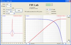
Back to FIR filtering, what do you think about linear-phase Neville-Thiele kernels as target functions?
I found that those (notably, 1st order NT) give a good overall compromise :
- compact kernels with low overshoot and low ringing
- sort of a "continuously rising filter order"-type of magnitude response
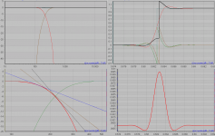
Attached a four-pic screenshot detailing the properties of a 1st oder NT at 215Hz.
Observations from top left graph, then clockwise :
- magnitude response, course. The restricton of the XO range to one octave left and right of center is clearly visible
- step responses of LP(red), HP(green), SUM(blue), delayed HP(brown) and finally sum(black) of the latter with the LP. In the mag plot we can see the delay causes a small broadband dip.
- the LP kernel impulse reponse. Has some kind of smooth "gaussianess", only a slight, 7% overshoot. Now, note the similarity of this kernel impulse to the "error shape" seen on top of the ideal step for the LP + delayed_HP case. That's why the kernel properties may be heard in some way (off-axis)**1. A Gaussian Pulse will not have a tonal character, rather it will sound like "noise pulse" (with a pitch sensation, still). The skewed, off-axis NT sum step shows some slight tonal ringing but still looks benign (try other XO functions to see). One might identify three periods of a shaped "215Hz" pulse with a fast decay at the skirts.
- close-up of the XO region, with 6dB, 12dB and 18dB slopes added for illustration, tangential to the LP response.
**1 : In minphase XOs the ringing (and it's complementary, "destructive interference" time sections in the step response) is also there, but it is masked off much better because it only post-rings.
Very interesting discussion going on here...
Back to FIR filtering, what do you think about linear-phase Neville-Thiele kernels as target functions?
I found that those (notably, 1st order NT) give a good overall compromise :
- compact kernels with low overshoot and low ringing
- sort of a "continuously rising filter order"-type of magnitude response
Attached a four-pic screenshot detailing the properties of a 1st oder NT at 215Hz.
Observations from top left graph, then clockwise :
- magnitude response, course. The restricton of the XO range to one octave left and right of center is clearly visible
- step responses of LP(red), HP(green), SUM(blue), delayed HP(brown) and finally sum(black) of the latter with the LP. In the mag plot we can see the delay causes a small broadband dip.
- the LP kernel impulse reponse. Has some kind of smooth "gaussianess", only a slight, 7% overshoot. Now, note the similarity of this kernel impulse to the "error shape" seen on top of the ideal step for the LP + delayed_HP case. That's why the kernel properties may be heard in some way (off-axis)**1. A Gaussian Pulse will not have a tonal character, rather it will sound like "noise pulse" (with a pitch sensation, still). The skewed, off-axis NT sum step shows some slight tonal ringing but still looks benign (try other XO functions to see). One might identify three periods of a shaped "215Hz" pulse with a fast decay at the skirts.
- close-up of the XO region, with 6dB, 12dB and 18dB slopes added for illustration, tangential to the LP response.
**1 : In minphase XOs the ringing (and it's complementary, "destructive interference" time sections in the step response) is also there, but it is masked off much better because it only post-rings.
Attachments
Last edited:
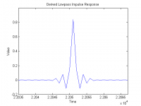
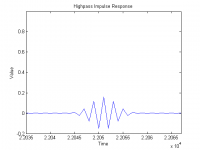
Unfortunately, that won't work well. When the Gaussian is centered at half the sampling frequency, its impulse response has a Gaussian envelope but every other sample changes algebraic sign -- it oscillates at the sampling frequency. See the attached graphs.With a subtractive filter can't the high pass section be used as the initial transfer function and then the low pass section derived from subtracting, instead of the other way around ?
Attachments
Very interesting, and certainly viable. And demonstrative of the huge variety of design decisions to be made. Does one sacrifice frequency response for impulse response? Does one opt for linear phase or minimum phase (or something in-between)? Does one worry about spatial lobing due to non-coincident drivers and non-identical phase in the crossover sections? Does one worry about attenuation rates and driver overload? Does one worry about perfect reconstruction?Back to FIR filtering, what do you think about linear-phase Neville-Thiele kernels as target functions?
I am very happy to see that the trend is away from simply designing filters completely in the frequency domain, without regard to time-domain effects. It remains to be seen what levels of compromise are ultimately deemed to be "acceptable".
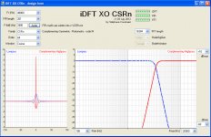
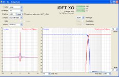
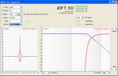
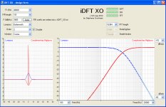
FIRs can deliver interesting complementary phase-linear crossovers. They can be incredibly sharp and selective, but on the other hand they exhibit presoot and ringing, and their attenuation curves are not symmetric when represented in log frequency axis. Some other varieties are less spectacular (they exhibit smaller slopes), but in exchange they don't exhibit preshoot and ringing, and their attenuation curves are symmetric when represented in log frequency axis. See attached .jpg. Which one would you try in first place?I am very happy to see that the trend is away from simply designing filters completely in the frequency domain, without regard to time-domain effects. It remains to be seen what levels of compromise are ultimately deemed to be "acceptable".
Attachments
-
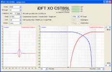 iDFT XO CSTBSL.jpg189.1 KB · Views: 65
 -
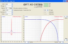 iDFT XO CSTBSi.jpg177.1 KB · Views: 61
 -
 iDFT XO CSRn 64th order.jpg179.1 KB · Views: 65
 -
 iDFT XO Brickwall.jpg171.8 KB · Views: 73
 -
 iDFT XO Asymptot 2nd order.jpg179.6 KB · Views: 60
 -
 iDFT XO Butterworth 2 double (=LR4).jpg181.1 KB · Views: 62
 -
 iDFT XO Bessel.jpg181 KB · Views: 62
 -
 FIR Lab Gauss.jpg181.1 KB · Views: 137
Which one would you try in first place?
Well, as you know, I do genuinely like the look of the straight line transition band! In my earliest experiments I tried a sine-shaped transition band too, as it was intuitively more rounded than the straight line transition but, again relying on intuition, I'm thinking that slope steepness should be kept in reserve for the extremities of the crossover region, so the linear-ish transition gets closer to that.
Would be nice to listen at them, switching the FIR coefficients on the fly. Always the same FIR length.I'm thinking that slope steepness should be kept in reserve for the extremities of the crossover region, so the linear-ish transition gets closer to that.
I'm considering eliminating any crossover generating some annoying sound, when listening to the woofer alone or the tweeter alone.
I'm curious to listen to the "Asymptot 2nd-order" XO because the woofer certainly will deliver a natural sound (if using a quality 3 inch or 4 inch driver, possibly two in d'Appolito), and the tweeter may exhibit a pleasing texture, with such "round" amplitude curve between 3 kHz and 5 kHz.
The Linkwitz-Riley 4th-order (two cascaded 2nd-order Butterworth) seems to materialize the gravity centre of the constellation. It still looks interesting, now that the FIR implementation permits a perfect reconstruction.
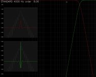
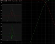
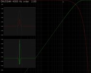
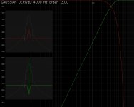
Might another graph be useful: a log representation of the magnitude of the impulse response vs. time? Using a linear display of the impulse response, it is not obvious that while some filters are good for ringing around the central impulse, they result in low level ringing that persists for longer.
I enclose some screenshots where this information is overlaid onto the normal impulse response images (I need to indicate dB etc. and I notice the frequency response dB markings next to the impulse responses are confusing.) Also, it might look better if only the peaks are used, joined into a smoother line.
I enclose some screenshots where this information is overlaid onto the normal impulse response images (I need to indicate dB etc. and I notice the frequency response dB markings next to the impulse responses are confusing.) Also, it might look better if only the peaks are used, joined into a smoother line.
Attachments
-
 STANDARD xo freq 4000Hz order 8.06.JPG183.6 KB · Views: 51
 -
 STANDARD xo freq 4000Hz order 3.97.JPG176.3 KB · Views: 54
 -
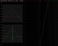 GAUSSIAN xo freq 4000Hz order 8.06.JPG181.6 KB · Views: 57
 -
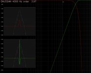 GAUSSIAN xo freq 4000Hz order 3.97.JPG174 KB · Views: 57
 -
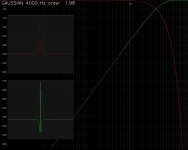 GAUSSIAN xo freq 4000Hz order 1.98.JPG175.5 KB · Views: 59
 -
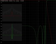 CHEBYSHEV xo freq 4000Hz order 8.06.JPG198.6 KB · Views: 66
 -
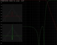 CHEBYSHEV xo freq 4000Hz order 3.97.JPG189.8 KB · Views: 75
 -
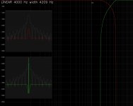 LINEAR xo freq 4000Hz width 4209Hz.JPG180 KB · Views: 63
Excellent! I was hoping that you would do this. It shows just how much ringing is actually occurring, even on waveforms that appear to be benign when viewed on a linear scale.Might another graph be useful: a log representation of the magnitude of the impulse response vs. time?
However, once again it appears that you are again referring to "Gaussian-like" waveforms (exp[-|x|^N], where N != 2) as "Gaussian". Please, to avoid misunderstanding, do not do that. It is only a Gaussian if N==2.
EDIT: Also, the difference between N==2 and N==4 is profound. Could you try N==3? Thanks.
Last edited:
However, once again it appears that you are again referring to "Gaussian-like" waveforms (exp[-|x|^N], where N != 2) as "Gaussian". Please, to avoid misunderstanding, do not do that. It is only a Gaussian if N==2.
Hi gberchin
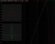
Yes, sorry. What is the best description? "Gaussian-derived"?
Edit: I enclose the results for Gaussian-derived (not too late to change that wording) at 2.0 (indicated as "Gaussian"), 3.0 and 4.0. Even the difference between a true 2.0 and the previous example of order 1.98 (or was it 2.02?) is noticeable.
(I have changed my UI to give me fixed steps of 0.2 in the order rather than a multiplying factor as previously, which was good for going up to very high orders quickly but a bit arbitrary in the step size).
Attachments
Last edited:
- Status
- This old topic is closed. If you want to reopen this topic, contact a moderator using the "Report Post" button.
- Home
- Source & Line
- PC Based
- The importance of crossover steepness