I thought I'd link to this thread here as its entirely relevant. Also that the thread title in the digital forum isn't exactly representative of what the thread contains.
http://www.diyaudio.com/forums/showthread.php?p=1911785#post1911785
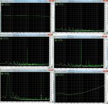
I have included, just for thoroughness a selection of measurements from the RightMark Audio Analyzer.
The results are fairly self explanatory and basically show extremely good performance. Comments in the other thread explain the noise level. The crosstalk however is down to the Preamp where there are ample situations for the signal to couple. I use a relay to swap the signal over from the headphones to the loudspeakers and with headphones selected bleed through is easily heard from the loudspeakers. This is one issue I will attempt to solve by better positioning and routing of signals if I ever rebuild the boards. The original design wasn't built in mind of the later additions so there are some unshielded wires all over the place. The overall level of -99dB from RightMark isn't exactly shabby, but this does deteriorate quite a bit as frequency increases.
The distortion can quite obviously be better then the overall 0.0009% figure RightMark says, it just requires some fiddling around with values until you hit on the right combination. RightMark requires you set input levels to specific value before it will start, so it was a little limiting in that respect, nevertheless 0.0009% isn't something to complain about.
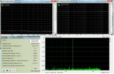
I have included in the last image a Jitter test from ARTA, I'm not entirely sure if that's how you're supposed to use that function. If it is then the jitter is seemingly non existent
The sound mirrors the results, its excellent.
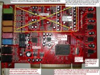
Everything is powered by Super regulators with the main transformer, rectification and smoothing caps in a box external to the PC. The I2S signal I take from the sound card is buffered by a 74LVC126AD mainly to protect the sound card and to ease the load on the VIA chip. I blew up one Revolution 7.1 entirely by accident and I'm still not sure how. At least with that chip in the way it might get destroyed instead of the sound card, it's better to lose a 25pence chip then a card costing £70.
http://www.diyaudio.com/forums/showthread.php?p=1911785#post1911785
I have included, just for thoroughness a selection of measurements from the RightMark Audio Analyzer.
The results are fairly self explanatory and basically show extremely good performance. Comments in the other thread explain the noise level. The crosstalk however is down to the Preamp where there are ample situations for the signal to couple. I use a relay to swap the signal over from the headphones to the loudspeakers and with headphones selected bleed through is easily heard from the loudspeakers. This is one issue I will attempt to solve by better positioning and routing of signals if I ever rebuild the boards. The original design wasn't built in mind of the later additions so there are some unshielded wires all over the place. The overall level of -99dB from RightMark isn't exactly shabby, but this does deteriorate quite a bit as frequency increases.
The distortion can quite obviously be better then the overall 0.0009% figure RightMark says, it just requires some fiddling around with values until you hit on the right combination. RightMark requires you set input levels to specific value before it will start, so it was a little limiting in that respect, nevertheless 0.0009% isn't something to complain about.
I have included in the last image a Jitter test from ARTA, I'm not entirely sure if that's how you're supposed to use that function. If it is then the jitter is seemingly non existent
The sound mirrors the results, its excellent.
Everything is powered by Super regulators with the main transformer, rectification and smoothing caps in a box external to the PC. The I2S signal I take from the sound card is buffered by a 74LVC126AD mainly to protect the sound card and to ease the load on the VIA chip. I blew up one Revolution 7.1 entirely by accident and I'm still not sure how. At least with that chip in the way it might get destroyed instead of the sound card, it's better to lose a 25pence chip then a card costing £70.
Attachments
Hi,
Recently I wrote to you a private email asking about interfacing DAC to PC via I2S interface, I received no response.
I wonder whether you can direct me to a design website where I can find some info. Also you said in some of you posts that I2S interface is superior to USB can you elaborate on that.
Cheers.
Hi,
Recently I wrote to you a private email asking about interfacing DAC to PC via I2S interface, I received no response.
That's most odd I don't have any PMs on the new site, neither have I received any emails. The only thing I can think is that hotmail shoved it into the junk folder
The simple way to do this is with a decent sound card. What you're after is one with separate DAC chips from the main PCI interface chip. I use a M-Audio Revolution 7.1.
Looking at the card and some reviews I could see that it used a AK4381 DAC for the front two channels.
http://www.datasheetcatalog.org/datasheets/270/137256_DS.pdf
Looking at the data sheet you can see that pins 1-4 carry the master clock, bit clock, data and LR clock. Conveniently, not too far away from the DAC chip, the 7.1 carries all these lines to another layer on the PCB, giving easy access to a point you can solder some wires onto.
All you need to do is hook up pins 1-4 from the AK chip to the correct pins on another DAC chip.
For example the PCM1794 accepts the 4 data streams on pins 4, 5, 6 and 7.
4 accepts the LR clock.
5 the data stream.
6 the Bit clock
7 the master/system clock.
If I was starting out I'd probably choose one of the ASUS Xonar cards. These already have some decent TI chips for their conversion anyway and should give you an easy job of extracting the 4 data lines, plus ensuring compatibility. They also accept a separate feed from the power supply via a floppy power connector. This would allow you to easily power the Xonar from anything you want.
Of course if I was willing I could rip up the Revolution and power it directly from the super regulators. This however would stop it working by itself, which I'd rather not do.
The chips and specs of the Xonar cards are already very similar to what I've built myself, so I'd be interested in hearing what they sound like in their vanilla form. The change from the M audio card to the first DAC I wired up to it was not subtle in any way though and made the M audio sound totally flat and lifeless in comparison.
ESI have a card called the Juli@ that already has different options of how you can configure the card. It uses the same VIA chip to interface with the computer as the M audio cards.
An externally hosted image should be here but it was not working when we last tested it.
But as you can see from that picture, it appears that they will most likely route the I2S signal from the main board to whatever you decide to plug into it. This isn't 100% definite mind you as the VIA chip can output data in another format besides I2S. If you can see what DAC chips the ESI uses you'd be able to ensure compatibility. From that picture it looks like they use AK DACs too.
I wonder whether you can direct me to a design website where I can find some info. Also you said in some of you posts that I2S interface is superior to USB can you elaborate on that.
I don't really know of any website, I just had the idea one day when looking at the M audio card and thought, well why can't I do that? So I did, and it worked
As far as I know, the USB interface doesn't allow you to synchronise the data stream with the master clock inside the computer. Instead the interface chip has to extract the clock itself. I did a bit of reading around and found someone saying that the PCM2706/7 chips had huge amounts of jitter, like 2000ps. Also TI doesn't mention an exact figure in the data sheets and you can bet if it was something to shout about, then they would. They seem to go out of their way to tell you their S/PDIF receiver, the DIR9001, can extract the clock with only 50ps of jitter. But no mention with the PCM2706?
Interestingly though, I am building a bit of kit for my Aunt that uses the PCM2706 and it's almost finished. The design starts out with the PCM2706 then feeds the Bit/LR and data lines into a SRC 4192 that upsamples the signal to 24 bit 96 khz and reclocks it before sending it to a PCM1794. I/V and then summing takes place before feeding a pot, then a headphone amp based around a TPA6120. She was so impressed when she heard my system on headphones that she immediately enquired as to what was necessary.
She only has a laptop so the most practical approach was using a USB chip. I have briefly listened to it when I was checking that it worked and it sounded more then acceptable. In the next couple of weeks or so I'll probably make a post detailing it with some measurements.
My only gripe with TI is that those USB chips are USB 1.1 that has a limit of 12 Mbit/s. USB 2 came out in 2001 according to wikipedia with a new max transfer rate of 480 Mbit/s. With USB 3 on the horizon with a data rate of 5.0 Gbit/s, I hope TI make a new series of chips. With a data rate like that I'd imagine they could do something snazzy to really improve over the 270X series. Not that they released 24 bit 96/192 khz versions with USB2, but here's hoping.
Last edited:
Nice implementation and comparison 5t Element, thanks!
I've wanted to try for some time a similar configuration with an akm based soundcard. Do you have some more details on the clock scheme of the revolution? Is it PLL based?
Thanks!
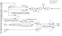
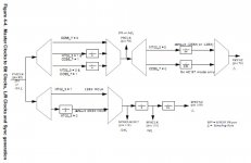
From what I can tell it isn't. The chip itself has inputs for two clocks/crystals depending on what sample frequencies you wish to use. The Revo uses a 49.152Mghz crystal for 32/48/96 and 192 khz and a 22.5792Mghz for 44.1khz and its multiples.
The data sheet implies that it uses dividers of these incoming crystals to derive all the clock frequencies that it and any other digital devices may require.
It specifies that you can drive these inputs with PLLs instead if you wish.
Of course this could just be my ignorance, the internal workings of digital chips isn't exactly something I'm good at. The data sheets don't mention anything specifically related to how the clocks are derived, except with a couple of flow charts. Now of course the blocks used could be of a standard design that represents something I am unaware of.
Attached are two images from one of the data sheets regarding clock generation.
I have always wondered if it would be possible (and by this I mean easy to acheive) to change the clocks the Revo uses.
Attachments
Thanks for the answer. Someone on this forum, (ID klaus if I remember) did some mods to a http://www.elitebastards.com/index.php?option=com_content&task=view&id=278&Itemid=27&limitstart=2.
The design is similar to your card. He stated trying to mod the clock but he would get some kind of time warped playback. Like when you hold a vinyl disk from spinning. I think he was using a tent clock also...
The design is similar to your card. He stated trying to mod the clock but he would get some kind of time warped playback. Like when you hold a vinyl disk from spinning. I think he was using a tent clock also...
Attachments
Thanks for the answer. Someone on this forum, (ID klaus if I remember) did some mods to a http://www.elitebastards.com/index.php?option=com_content&task=view&id=278&Itemid=27&limitstart=2.
The design is similar to your card. He stated trying to mod the clock but he would get some kind of time warped playback. Like when you hold a vinyl disk from spinning. I think he was using a tent clock also...
Sounds like he got the wrong clock speed then and everything played back slowly as a result. I have had similar things happen when an ASIO player got stuck with the wrong sample frequency and it played back at half speed
I can't find a thread about what he did, and searching for 'tent' and the ID 'klaus' comes up with nothing.
Last edited:
Sorry,
I've confused this thread here on diyAudio with this one over at diyhifi. Both are highly informative. The second is about installing the tent clock.
I would really like to know if these PCI card are bit perfect.. From what I've read so far, all of them seem to have a PLL recovery scheme, in which the Master clock is the PC. The correct implementation would be the master clock in the dac, and the PC should be slaved... But again, I don't have a good understanding of these architectures either..
The USB thingymabob is all finished I'll add, I gave it to my brother to put it through its paces.
It's worked flawlessly when plugged into 4 different PCs. The two laptops I've tried it with however... Neither detect it if they are running on the battery, which is strange as it only draws 20mA, no matter how I set the power settings. Plug in the power supply and its a different matter.
Playback on one laptop is fine, whereas the other one stutters when trying to play music, stream off you tube, or watching videos. Play a computer game though and its fine. World of warcraft, warcraft three and a simple game my brother made all have no problems. I just hope it doesn't have any problems with the laptop of the person I made it for.
Sorry,
I would really like to know if these PCI card are bit perfect.. From what I've read so far, all of them seem to have a PLL recovery scheme, in which the Master clock is the PC. The correct implementation would be the master clock in the dac, and the PC should be slaved... But again, I don't have a good understanding of these architectures either..
Not in any card I am familiar with!
The usual model is that the PCI interface loads its shift register from a buffer that is refilled by triggering a DMA cycle on the PCI bus. The shift register is clocked out by the on card crystal (often using a PLL to derive the appropriate clock rate from a single rock).
This is certainly how most of the ICE1712 based things work (some have additional PLLs to deal with locking to things like SPDIF inputs, but that is a detail.
As MCLK always has to be supplied to the converter chip from an external source, I don't see how you easily improve on this arrangement (other then possibly by upgrading the entire clock generation scheme to avoid using a crystal referenced PLL as the master clock (use two rocks instead with good quality divider chains, but it would be a lot of faffing about)).
Nothing I am aware of uses any of the various clocks available on the PCI bus as a clock source for the converters.
Regards, Dan.
Thanks for clarification Dan,
So that means that basically if I settle to one sample rate (say 192Khz) and I put a good clock, a good output stage and feed all this with a good PSU, I should be done..
I really have to get myself one of the new sound cards.. I think I just delayed the moment hoping some USB based miracle to happen... (asynchronous if possible )
So that means that basically if I settle to one sample rate (say 192Khz) and I put a good clock, a good output stage and feed all this with a good PSU, I should be done
..I really have to get myself one of the new sound cards.. I think I just delayed the moment hoping some USB based miracle to happen... (asynchronous if possible
)Ice1712/24 cards do not use jittery PLL for clock generation, but two crystals. The driver is responsible for setting the chip's internal clock dividers according to current sample rate. Cards with external clock scheme provided by Xilinx CPLD (Juli, Infrasonic Quartet) do not use the internal dividers, but dividers are programmed in the CPLD and the driver instructs the CPLD via GPIOs of ice1724. From the clock POV it is virtually the same, the Xilinx setup provides independent clock for reliable detection of SPDIF input sample rate, and the card can output 176,4kHz on SPDIF output unlike internally-clocked ones (probably a bug in ice1724).
- Status
- This old topic is closed. If you want to reopen this topic, contact a moderator using the "Report Post" button.
- Home
- Source & Line
- PC Based
- My latest.