Am building the stereo amplifier in dual mono configuration. Is it ok to use speaker protection with common ground, or do i need dual speaker protections as well?
I have used a few protection boards that I got from Ebay. The ones I used had good quality HD relays- Omron, I believe. If you get a stereo speaker protector, it should be using a double pole relay. That way the 2 channels can be completely isolated. The circuitry on the protection board will need to be powered from one channel, meaning that it will be connected to that channel’s PS ground. So, if that breaks your definition of dual mono you need 2 protection boards. You could also add another small PS to power the protection board.
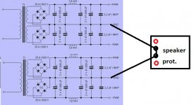
You will only be interrupting the hot output of the amplifier channels and the common side is not interrupted.
I already have the protection board like this:
UPC1237 30A High Power Stereo Speaker Protection Board Module AC 12V-16V | eBay
It have common ground for both channels.
So my question is, it is ok to wire both power supply grounds from dual mono amplifiers together?
UPC1237 30A High Power Stereo Speaker Protection Board Module AC 12V-16V | eBay
It have common ground for both channels.
So my question is, it is ok to wire both power supply grounds from dual mono amplifiers together?
Attachments
You don’t need to run your speaker ground wires through those boards. You only need to run the hot wires through the relays and provide power to the boards. The board looks similar to what I used in my Aleph J but I have omron relays.
I don’t want to pull the amp apart to look, but from memory the ground connections on the terminal strips are just a pass through and the in and out connections are for the + speaker connections. You do not need to connect your amp grounds to the board. Simply insert the protection board relays into the wire from the amp output to the speaker terminal. You need to power the board, which can be done using another transformer for complete isolation or by using the AC from the amp power supply if it is close enough in value. You may need to increase the size of the heatsink on the 7812 if you use higher than 16vac. I used the 20vac in the aleph J and increased the heatsink size so it didn’t run too hot.
I don’t want to pull the amp apart to look, but from memory the ground connections on the terminal strips are just a pass through and the in and out connections are for the + speaker connections. You do not need to connect your amp grounds to the board. Simply insert the protection board relays into the wire from the amp output to the speaker terminal. You need to power the board, which can be done using another transformer for complete isolation or by using the AC from the amp power supply if it is close enough in value. You may need to increase the size of the heatsink on the 7812 if you use higher than 16vac. I used the 20vac in the aleph J and increased the heatsink size so it didn’t run too hot.
It’s been a while since I did this work. I should have had a closer look at my documentation for my implementation of the board. I used it as stereo board in an Aleph J and also in 2 monoblock F5t3 amps as mono. Yes that is correct, but you still do not need to run your speaker return to common output current through the board. You can wire it back to the power supply grounds as you indicated in your drawing. If the protection board is truly a common ground you could also connect the 2 ps together directly and run a single wire to the protection board. Have you had any hum issues running the 2 channels completely isolated ?
Of course, the best option (if you don’t a soft start scheme) is to buy the board in the store:
Soft Start & Speaker Turn-On Delay / DC Protector Combo – diyAudio Store
This is the only time I can shamelessly promote a product on the forum.
Soft Start & Speaker Turn-On Delay / DC Protector Combo – diyAudio Store
This is the only time I can shamelessly promote a product on the forum.
I already have the protection board from my old project. And yes, i have some product from diyaudio store and they are great. Only the shipping costs are a bit high to Europe.
So is there any safety issues if i use my old speaker protection board and connect both grounds from dual mono amplifiers to common speaker protection ground?
So is there any safety issues if i use my old speaker protection board and connect both grounds from dual mono amplifiers to common speaker protection ground?
To keep your grounds isolated from one channel to the other, I would use two speaker protection boards, one for each channel.
Of course, each channel's PSU ground then needs its own CL-60 or diode bridge connection to chassis ground / PE. Grounds come together only after their respective CL-60s / diode bridges. That's the way I built my double mono F4.
Regards, Claas
Of course, each channel's PSU ground then needs its own CL-60 or diode bridge connection to chassis ground / PE. Grounds come together only after their respective CL-60s / diode bridges. That's the way I built my double mono F4.
Regards, Claas
Hi folks, it's been a while. A "crippled" f4 question. Can anyone tell me what properties of a preceding stage make it acceptable to remove the input buffer from the circuit?
In recently added a EML-20A based dht preamp with a transformer-coupled output and the jump in realism has me interested in simplifying circuits whenever possible.
Thanks and hope you all are survive out there.
In recently added a EML-20A based dht preamp with a transformer-coupled output and the jump in realism has me interested in simplifying circuits whenever possible.
Thanks and hope you all are survive out there.
Rout - no more than 100R
Thanks so much ZM. And damn, I'm at 375R.
I‘m pretty much convinced it does (I actually feed my F4 with just a 2V output „pre-amp“ and it’s not loud but nice)... others have already done so, and there’s more to be gained with output-xformers, or by changing some resitors which I don’t recall which ones or what values.
See posts 1221 ff or use google site:diyaudio.com wayne's ba18 gain resistor which returns post nr 1233
Most probably ba-3 would be the more classical way, though.
See posts 1221 ff or use google site:diyaudio.com wayne's ba18 gain resistor which returns post nr 1233
Most probably ba-3 would be the more classical way, though.
Hi folks, it's been a while. A "crippled" f4 question. Can anyone tell me what properties of a preceding stage make it acceptable to remove the input buffer from the circuit?
In recently added a EML-20A based dht preamp with a transformer-coupled output and the jump in realism has me interested in simplifying circuits whenever possible.
Thanks and hope you all are survive out there.
Hi.
Attached is the F4 without the input buffer and a few questions:
1 - is it a working schematic or do you thing is better to remove the input buffer in a different way?
2 - i don't understand why the input caps are so big, they would see a minimum input impedance of circa 36R (assuming 10Hz of low frequency corner), that it seems to me too low. The input would have a minimum of 18 ohm...is there anything i don't see in the schematic?
3 - do you really think the fet input buffer is a limit in any way? I would replace it with a tube buffer with an output impedance of 100R circa.
I'm pulling the trigger on F4's stuff in the store and would like to know what do you guys think.
Carmelo

Last edited:
Does Wayne's BA 2018 line stage have enough voltage gain for the F4? Or would the BA-3 be better?
One of things I drive drive my F4 with is a dac with a grounded grid amplifier (12AU7) putting out a measly 2V. For me it’s plenty with most program material driving a Martin Logan ELS (Montis).
Hi.
Attached is the F4 without the input buffer and a few questions:
1 - is it a working schematic or do you thing is better to remove the input buffer in a different way?
2 - i don't understand why the input caps are so big, they would see a minimum input impedance of circa 36R (assuming 10Hz of low frequency corner), that it seems to me too low. The input would have a minimum of 18 ohm...is there anything i don't see in the schematic?
3 - do you really think the fet input buffer is a limit in any way? I would replace it with a tube buffer with an output impedance of 100R circa.
I'm pulling the trigger on F4's stuff in the store and would like to know what do you guys think.
Carmelo
View attachment 947432
Ok.
Here there are most of my answers:
https://www.firstwatt.com/pdf/art_ba_3.pdf
The TL431 I believe it is the "culprit" of the low input impedance.
- Home
- Amplifiers
- Pass Labs
- F4 power amplifier