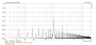
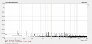
Here is my 1W into 8R. It is right on the spec from the F4 product manual, at 0.05% THD. However, the noise is too much. Looks like multiples of the line frequency. Hmmm... might be my layout and wiring. There is no hum. Very slight buzz can be heard if I put my ear on the 110 db/W horns. Nothing at the listening position.
I also checked the mV on each source resistor, all good. They don't match exactly, but aren't too far off.
Thoughts?
I also checked the mV on each source resistor, all good. They don't match exactly, but aren't too far off.
Thoughts?
Attachments
Here is my 1W into 8R. It is right on the spec from the F4 product manual, at 0.05% THD. However, the noise is too much. Looks like multiples of the line frequency. Hmmm... might be my layout and wiring. There is no hum. Very slight buzz can be heard if I put my ear on the 110 db/W horns. Nothing at the listening position.
I also checked the mV on each source resistor, all good. They don't match exactly, but aren't too far off.
Thoughts?
Wow, that noise is crazy. Around -50dB to -70dB relative to the signal is bad.
Should be aiming for -80dB to -100dB. -80dB bare minimum relative to the fundamental signal at 1W.
Seems like it might be from the AC mains wiring.
Do you have X Caps installed across the mains?
Even better get a top quality filtered IEC connector eg schurter etc. Get the nickel plated steel housing one not Aluminium.
Are all your caps in the power supply in good condition?
What bridge rectifiers are you using?
What does you power supply look like?
Then obviously wiring layout, bad connections etc.
Last edited:
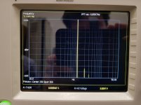
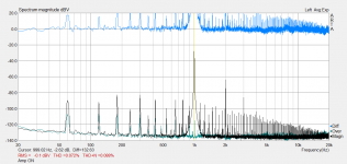
For reference here is mine 0.0029% and no noise down to -100dB, there is noise once you get below that though.
Sounds absolutely beautiful.
Well my amp is not a stock build, but I posted just to show what is achievable.
Let's get your amp fixed. It should sound beautiful.
Sounds absolutely beautiful.
Well my amp is not a stock build, but I posted just to show what is achievable.
Let's get your amp fixed. It should sound beautiful.
Attachments
Last edited:
Here is my 1W into 8R. It is right on the spec from the F4 product manual, at 0.05% THD. However, the noise is too much. Looks like multiples of the line frequency. Hmmm... might be my layout and wiring. There is no hum. Very slight buzz can be heard if I put my ear on the 110 db/W horns. Nothing at the listening position.
I also checked the mV on each source resistor, all good. They don't match exactly, but aren't too far off.
Thoughts?
If you remeasure with the least amount of attenuation necessary how does the measurement look?
Just want to be sure the result is fairly consistent.
Checked JFET Vp of other JFETs from same batch, looks good. These JFETs have been gathered many years ago from members Zhou, Spencer, and others. Some from Mouser. I also have some from LS for testing, but not enough for a full F4.
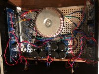
Pico, you may be on to something there with the PS caps and bridge rectifiers. The caps are 18,000 uF bought many years ago from diyaudio members. Rectifiers are from many years ago too, with some pulled from other amps. They are the standard 200V, 35A types that bolt to the chassis. I'll check that the rectifiers work.
PS is exact copy from FW manual. See pic. I do have a cap across the line terminals.
Yes, I can do a better job with the wiring. I was too eager to finish it and hear it.
Attachments
Last edited:
Try twisting the transformer secondary wires, and any other wires together.
Keep all signal wires short and routed far away from any ac mains wiring, and away from the transformer. Looks like you have dc wiring in very close proximity to the transformer.
If the caps are old, being used for the first time maybe leave the amp on for a day or two and remeasure it. Sometimes they come good after some usage.
Last edited:
Yes, checked bias again this morning. It has now run for about 4 hours. All source resistors are in the 220 mV range. JFET source resistors are drawing 8 mA. I'll let it run for the day as you say.
I suspect it is the PS caps or the bridge rectifiers. I have a hard time believing this much noise can be picked up through the wiring.
Heatsinks are getting toasty at about 50 C. The transformer is quite warm to the touch. It is 600 VA. I don't why it is getting so warm.
I suspect it is the PS caps or the bridge rectifiers. I have a hard time believing this much noise can be picked up through the wiring.
Heatsinks are getting toasty at about 50 C. The transformer is quite warm to the touch. It is 600 VA. I don't why it is getting so warm.
Last edited:
I have a hard time believing this much noise can be picked up through the wiring.
Neatness counts. A lot. So does routing.
Heatsinks are getting toasty at about 50 C. The transformer is quite warm to the touch. It is 600 VA. I don't why it is getting so warm.
It's sitting in a hot box, it's going to warm up as well.

Yes, checked bias again this morning. It has now run for about 4 hours. All source resistors are in the 220 mV range. JFET source resistors are drawing 8 mA. I'll let it run for the day as you say.
I suspect it is the PS caps or the bridge rectifiers. I have a hard time believing this much noise can be picked up through the wiring.
Heatsinks are getting toasty at about 50 C. The transformer is quite warm to the touch. It is 600 VA. I don't why it is getting so warm.
Grounding schemes are very important to get right. The large currents flowing in the power supply filter circuit can induce large voltages in high impedance low level signal lines. If PS filter current is flowing through a signal ground it will essentially cause an unwanted input voltage.
Power transformers are rated for power output at a specified temperature rise. Sometimes it is 50c and some are 70c. Drawing 300w from a 600w transformer with a 50c spec you will see a rise of 25c above ambient. If your case is running at 40c internally, the transformer would be at 40c+25=65c. So it will feel warmer than the amp chassis even when used at a fraction of it’s output.
Heatsinks are getting toasty at about 50 C. The transformer is quite warm to the touch. It is 600 VA. I don't why it is getting so warm.
What is the temperature rise above ambient of the transformer?
Ambient temp inside chassis might be 45C, you could have a 10C rise which would bring the transformer to 55C.
It's worth measuring these things to see if there is a problem or not.
There is always the possibility of dc on the mains.
Last edited:
I tend to agree, although there are things you can do to make improvements.I suspect it is the PS caps or the bridge rectifiers. I have a hard time believing this much noise can be picked up through the wiring.
If you got a piece of right-angle steel say 2mm thick and mounted the transformer on it with the vertical wall facing the direction of the power supply, that could improve things a bit. Shielding the transformer from the dc wiring loom.
Last edited:
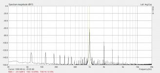
Made some progress today. Moved the rectifiers back and away from the DC out from the PS board. That did it some good, the noise is not so bad now, though it is there.
Here are some more measurements. I adjusted the scaling and levels.
1. First, the environment noise. This is with the amp OFF.
2. Amp ON. A lot better than yesterday.
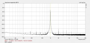
3. Loopback with RME.
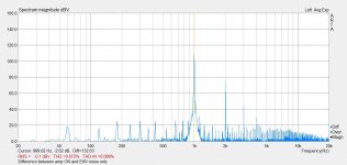
4. Difference between environment only and amp ON.
Ignore the THD. After running it for an hour, it drops to around 0.045%. I was turning it on and off for these measurements.
Listened to it in the evening. It is a lot better. The glare is mostly gone. Compared to the M2, it has more bottom end. Sounds like someone secretly put a couple db shelf starting at 100 Hz. All good there. The liquid clarity is there, like the M2. The M2 also romanticizes just a tiny hint, that's the transformer talking. The F4 seems to be neutral there and I wish for more top end clarity. I suspect there is room for improvement on the noise and that should improve things.
Thanks for all the help, Pico, everyone! I really appreciate it. Hope to keep going.
Here are some more measurements. I adjusted the scaling and levels.
1. First, the environment noise. This is with the amp OFF.
2. Amp ON. A lot better than yesterday.
3. Loopback with RME.
4. Difference between environment only and amp ON.
Ignore the THD. After running it for an hour, it drops to around 0.045%. I was turning it on and off for these measurements.
Listened to it in the evening. It is a lot better. The glare is mostly gone. Compared to the M2, it has more bottom end. Sounds like someone secretly put a couple db shelf starting at 100 Hz. All good there. The liquid clarity is there, like the M2. The M2 also romanticizes just a tiny hint, that's the transformer talking. The F4 seems to be neutral there and I wish for more top end clarity. I suspect there is room for improvement on the noise and that should improve things.
Thanks for all the help, Pico, everyone! I really appreciate it. Hope to keep going.
Attachments
Last edited:
Working on improving routing, Jim. The 4U chassis is tight with a 600 VA trafo.
Pico, the 4U chassis is more wide than long, so layout is becoming tight. Have to put the bridges to the side of the transformer AND away from the PS board. Then have to route wires from the sides to the PS board. Could I mount the PS board above the transformer?
I don't have a shelf angle right now, but that's another consideration. Thanks!
Transformer top plate was at 45 C I think after a good 4 hours. Transformer felt cooler than that.
Grounding is as per the FW supply circuit. Only place signal ground meets earth is at the chassis and there is a thermistor providing a small voltage barrier between signal ground and chassis/earth.
Last edited:
- Home
- Amplifiers
- Pass Labs
- F4 power amplifier