Finally bought some 50uF motor caps to add to my power supply. Do they need to be installed upright, or can I lay them on their sides? The latter gets the wires a little closer to where they need to go in my case...
Mount the capacitors so that their wires to the amplifier PCBs are short.
Last edited:
I completed my F4 and started one channel using a power supply that I had previously used, for a few months, to power my F5 built on Peter Daniel's boards.
...
Hi Grimberg,
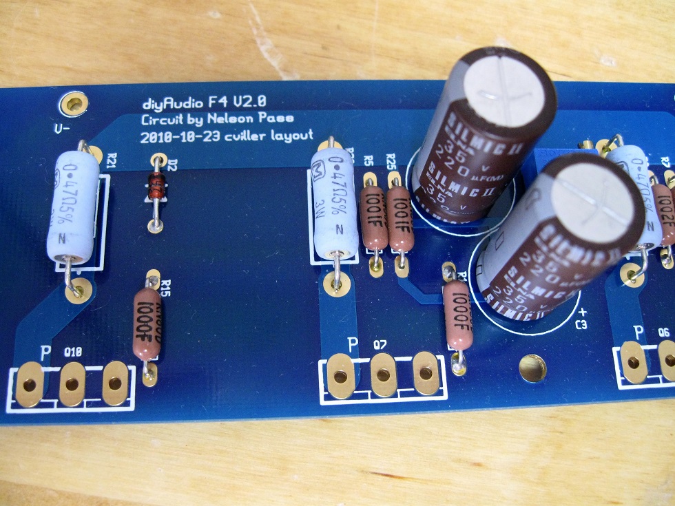
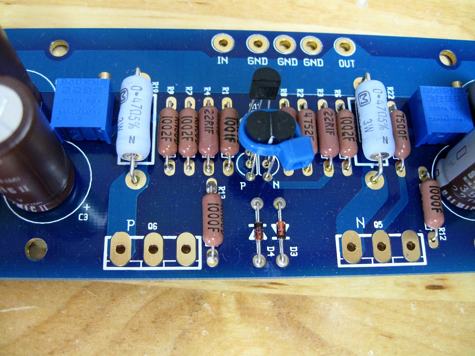
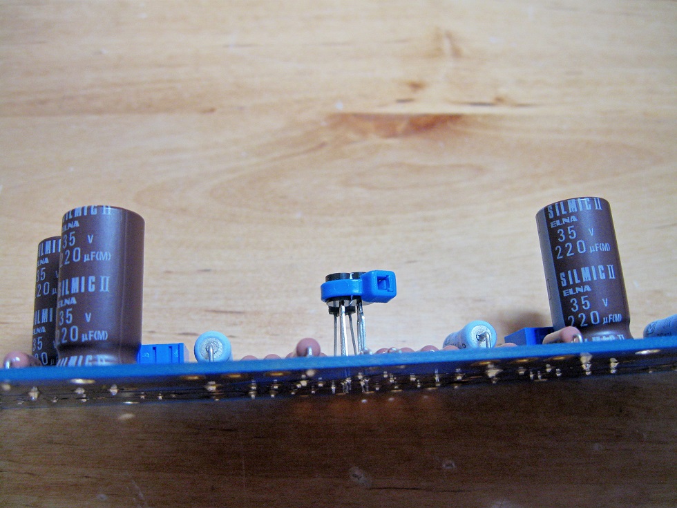
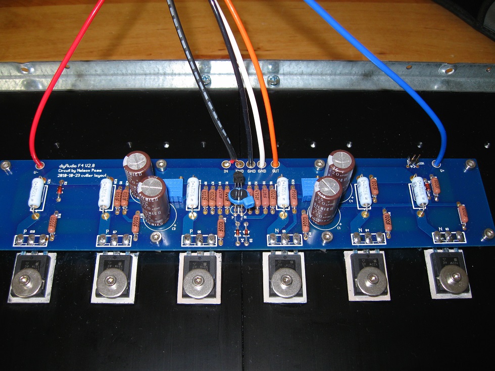
A perfect installation. The trimpot you're using. Is it Bourns 3299P? The trimpot orientation makes it very easy to adjust from above.
~Kecap
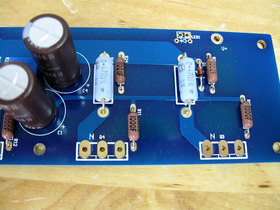
My recommendation is to solder the side of the components so that they connect *directly* to the trace that is carrying the current.
The other side that does not have the trace is then a mechanical connection.
Agreed. Looks a little light on solder. If you read about my issues in the F4 build guide, you'll see I had some issues because I didn't let the solder fully flow through the holes. It kind of looks to me like you've got the potential for that issue in a few places too...
See my posts starting here and continuing for a few pages (along with pictures of the boards pre and post issue): A guide to building the Pass F4 amplifier.
F4 Current limitation
I am wrapping my head around the current limiting of F4, trying to understand the real reason.
The F4 manual states current limit as 5A per channel; however the recommended IRFP MOSFET transistors can go much higher; with 12A and 20A respectively and considering 3 pairs in parallel, it goes up to 36A. While some part of that current can not be used due to source resistors, still there is a large headroom to push more current than 5A.
As such, tapping into collective wisdom here") , would be great if someone could enlighten
, would be great if someone could enlighten
I am wrapping my head around the current limiting of F4, trying to understand the real reason.
The F4 manual states current limit as 5A per channel; however the recommended IRFP MOSFET transistors can go much higher; with 12A and 20A respectively and considering 3 pairs in parallel, it goes up to 36A. While some part of that current can not be used due to source resistors, still there is a large headroom to push more current than 5A.
As such, tapping into collective wisdom here
, would be great if someone could enlightenLongevity.
You could increase the current if you like, but there is diminishing returns, like everything, as well as a large increase in heat.
Me getting even more confused
Bear with me please, let me run my train of thought:
I was thinking just increasing the maximum current limitation would not change heat dissipation: this should be essentially playing with zener diodes I would assume? And the amp might only tap into that during dynamic swings etc.
On the other hand, what you describe makes sense for the class A bias current of the amp: as you increase it, the heat dissipation will increase as well.
On top: I would expect there is an interplay between the class A bias current and max. Current capability of amp:
- With standard 1.3 Amp class A bias, max current of amp is specified as 5 Amp (probably due to no feedback beyond this point distortion increase quite a lot)
- If one goes for 3 Amp class A bias, max current could also be increased: maybe close to 10 Amp (obviously given there is enough cooling/heatsinking etc.)
And having irfp devices with 1A class A bias should be all fine: as they are running on 1.3 Amp on a standard F5
Does it make sense?
Bear with me please, let me run my train of thought: I was thinking
just increasing the maximum current limitation would not change heat
dissipation: this should be essentially playing with zener diodes I would
assume? And the amp might only tap into that during dynamic swings etc.
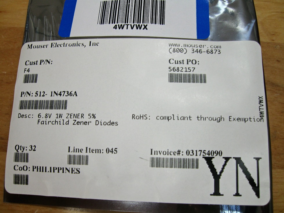
That is correct. The 1n4736 6.8V zeners will limit the current in two ways:
1) It will limit the voltage from the Gates to Output of a follower to 6.8V,
which is the Vgs plus the voltage drop of the Source resistor.
2) It will forward conduct as a regular diode approximately at the point
where the drive exceeds the total bias volts plus the 0.6V diode drop.
Mono Balanced Operation
I have just completed biasing of a second F4 amplifier. Now I wish to wire them up for mono balanced operation. I read and re-read Nelson Pass's Operation and Service Manual and found cviller's succinct description (#2789). But I'm still lost.
Is there a diyAudio member out there who can enlighten me with a more detailed walk-though on how to do this?
I'm using a Benchmark DAC3 HGC with XLR output as an option. By the way, the sound quality of a single F4 is spectacular. I've gone the route of 91A 300b tube amps and, more recently, the F6— a beautiful design. But the detail of the F4 is the best by far. I just need a little more power for my Dick Olsher's OB design using SAL speakers. How beautiful they are!
DIY all the way!
have XLR panel jack on back of each stereo F4
wire pin 1 to (any) RCA jack GND
wire pin 2 to hot of Right channel RCA jack
wire pin 3 to hot of Left channel RCA jack
connect XLR-XLR cable to output of your preamp
other end of cable connect in XLR jack on back of F4
positive output of Rch is your positive speaker wire connector
positive output of Lch is your negative speaker wire connector
do the same for other channel amp

I enjoy F4 very much. I switch back and fourth between M2 and F4. I use a dual PSU in external chassis. I guess the cable from psu to amp has some impedance. The motor run capacitors in F4 chassis makes the bass vibrant. On the other hand the treble in my Cornwalls take dive above 14k-16k. Especially after a while, warm tweeters?
I don’t know if a small capacitor in parallel of the motor runs affect the frequency. Bollocks or fact, could it be advised to put for example a 0.1uF in parallel to motor runs in F4? If so would any of Rifa paper-metal, Wima MKS4 or Kemet rms(pps) be good choice? Just to keep a low impedance?
PSU-caps: peh200 15kuF, esr 12-16mOhm, esl 22nH.
Motor runs in F4: 40uF(to low but doing some good work).
Help me to to think here
I have also considered a super tweeter and read, or heard, somewhere that F4 likes ribbon tweeter over dome(?)
Considering buying one of these super tweeters:
Fostex T90A
Viawe Audio GRT-145
I am grateful for any idea or advice.
why thinking at all - just put those 100nF caps and sleep better**
regarding supertweet - you need efficiency , so Fostex could be better than ribbon
if ribbon , think about second cheapest Fountek , first with Horn - around 100-120E pair in Eu
edit: found the type : Fountek NeoCD3.5H
edit edit: ** even if I think that only sleep is going to be better
regarding supertweet - you need efficiency , so Fostex could be better than ribbon
if ribbon , think about second cheapest Fountek , first with Horn - around 100-120E pair in Eu
edit: found the type : Fountek NeoCD3.5H
edit edit: ** even if I think that only sleep is going to be better
Last edited:
 I will read about the horn.
- Home
- Amplifiers
- Pass Labs
- F4 power amplifier