Two questions,
I came here to ask is a single stereo Aikido 6SL7/6SN7 is lacking anything as far as powering two F4 monoblocks?
The previous page has me somewhat motivated to give the BA-3 a try. I was given the boards and have most of the inexpensive parts. Two matched quad's from the recommended seller?.
I came here to ask is a single stereo Aikido 6SL7/6SN7 is lacking anything as far as powering two F4 monoblocks?
The previous page has me somewhat motivated to give the BA-3 a try. I was given the boards and have most of the inexpensive parts. Two matched quad's from the recommended seller?.
is Aikido having balanced output?
No.
Is it not an option to put something as low tech as a Y splitter cable that would work?
If there is a thread which helps explain the BA-3 preamp with a single ended to balanced output with photo's for us old folk, well I must have really bad ADHD because I've spent months looking. It is sort of out of the question after a discussion in the last hour over finances. If I won the lottery or can sold some old equipment then I might be able to buy two sets of matched quads.
I need a phono stage within two weeks, so repurposing the Aikido for that to provide the last dB's of gain might not be a bad use of it, especially since it has no selector or volume control. I might get by through the hot months with an amp that doesn't create as much heat while I work on some of the other projects.
I never thanked you for referring me to a particular turntable project about 16 months ago
 but needless to say I need to show my better half where the money for the new tonearm and cable went. Maybe she still has a headache from the sound of cutting slate.
Last edited:
Impedance of Infinity RS-IIIb speakers (assuming this is what you are planning on using) dips below 4 ohms. So you may want to configure your F4s in "Mono parallel connections" [see manual], in which case you can connect the Aikido output using a "Y" cable as you describe.
The Aikido pre is a good match to the F4. Lots of gain, peak-to-peak swing and very quiet. I enjoy mine very much.
Pierre
The Aikido pre is a good match to the F4. Lots of gain, peak-to-peak swing and very quiet. I enjoy mine very much.
Pierre
Impedance of Infinity RS-IIIb speakers (assuming this is what you are planning on using) dips below 4 ohms. So you may want to configure your F4s in "Mono parallel connections" [see manual], in which case you can connect the Aikido output using a "Y" cable as you describe.
agree on that
Salas 6v6 preamp
Can I use the bufferless version of the F4 with Salas' 6V6 preamp (gain version)
I believe this is the correct bufferless schematic on post 827:
UGS adventures
Can I use the bufferless version of the F4 with Salas' 6V6 preamp (gain version)
I believe this is the correct bufferless schematic on post 827:
UGS adventures
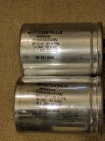
They are 28yr old. (9016 and 9006 date codes)
What's wrong with the caps already installed?
Jim,
Nothing wrong with the existing caps but just query if this freeby will give better result. Oh. I know now they are too old the the job. Will give them back.
Thanks
Albert
maybe already installed are 48yrs old ?

Choky,
At least not as old as I'm.
Albert
same here
one thing is if they're old , other thing is are they tired and worn and dry
try reforming them - just slab them to highest possible DC PSU you have (up to declared voltage) through 100K resistor and leave them connected that way for few days
then try them , nothing wrong with some testing fun
if you have a place in case , connect 50uF motor-run caps as bypass for final caps in filter section , that usually brings some speed and freshness
look at surplus places , sometimes you can find bargains
same here
one thing is if they're old , other thing is are they tired and worn and dry
try reforming them - just slab them to highest possible DC PSU you have (up to declared voltage) through 100K resistor and leave them connected that way for few days
then try them , nothing wrong with some testing fun
if you have a place in case , connect 50uF motor-run caps as bypass for final caps in filter section , that usually brings some speed and freshness
look at surplus places , sometimes you can find bargains
Thanks choky,
You said there might be chance to wake them up by charging them with the stated maximum voltage and series a 100k from the PSU.
I have a bench PSU with adjustable dual 25v. I'll try series both supplies and tune to the cap maximum voltage to try.
Thanks for the advice
Albert
Hi Zen Master ...
Just a little question, if i use jt-123-alch for input F4 (and i
hope to get bigger sound) so i need to connect output transformer
to input F4 (R1 1k) with / without change the schematic ?
If there is a change, can you let me know ... What is the part
need to change, move, connect or cut?
My input is unbalance / rca
Thank u before
Regards, jeffry
R1 in F4 r0.
Nice idea, something I intended to try at some stage... some day, when I've cleared my backlog of projects.
ZM will correct me if Im wrong, I'm not sure if it will drive the mosfets directly (3deep, maybe, 6 deep, don't know), but I would try inserting the transformer between R3,R4 and C1,C2.
Wire as autoformer, ground pin 8, drive pin 7, link 6&7, 4&5, 2&3, take output from pin 1.
Edit. You could then delete R24 R25 C3 & C4.
You may have to play with the transformer output loading.
Last edited:
Input/output transformer
Thanks a lot Zen, Can you give me a little enlightment about
If we look for jt-123-flpch or lundahl lundahl oleh 1690 they ratio
are 1+1:1+1 so these mean 1 input will 2x output ?
So if i look on lundahl series ll 1676 and ll 1677 they ratio were
1+1:2+2 and 1+1:4+4 so if Will 4x output and 8x output ?
Can we use 1pcs ll 1676 with ratio 1+1:2+2 for balance input?
So we will get 2x output for every input?
Pls correct me if im wrong
Thank you Zen, br
- Home
- Amplifiers
- Pass Labs
- F4 power amplifier