I replaced the TL431, but it doesn't help.
Since then I tried a lot of stuffs, and finally be able to narrow down the problem, which is at C1. Here are the gist.
- The reason that the DC fluctuation at output symptom is voltage across TL431 isn't as still as it can be.
- When I soldered a 220µF electrolytic capacitor at C1, the problem appears.
- Replacing the 220µF electrolytic capacitor does not solve the problem.
- Soldering a 47µF film cap largely solved the problem, but soldering 220µF electrolytic capacitor on it brings the problem back.
- If I connect the 220µF electrolytic capacitor through wire with alligator clips, the problem disappears.
- If I clip the leads of the 220µF electrolytic capacitor directly without the wire, the problem came back.
So I thought, may be I need the resirtance of the wire. So I tried adding a resistor (1Ω, 5Ω and 22Ω). If I clip the resistor leads directly, the problem remains. If I connect the resistor through wire with alligator clips, the problem disappear.
Why is it that the wire with alligator clips seems to posses magical property? Any ideas?
Btw, just for reference, I think I found the cause of the problem.
As mentioned I did everything that I can imagine around the TL431 with no luck. I got stuck and one thing lead to another, I neglected this project. Then one day I got an epiphany, and true enough the wildish voltage fluctuation went away when the 2SK170 is disconnected. So it's probably fried.
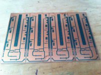
Sorry. missed some questions. These boars are 6" long. THey will allow a bias at my chosen point of .5a/fet for total of 1.5a Iq. The SE bias will be about 1/10th of that. With a bridged amp , we are talking something like 30W class a into 8R, similar to the Firstwatt series. This is mainly a test of the Se bias concept as well as the FE boards that will be pushing it along. AB power will be higher due to available rail voltage. On my expected set of speakers, this will be an exuberant amount of power. That being said i may use more fets in the end.
PDYN -
1) So the AC component (the music signal) moving across the cap is very small, and the cap stays almost completely charged at all times.
2) Yes, you could, but as you say, it would be a re-design of the circuit and hold no resemblance to an F4 at all. Look at the Burning-amp 1 or BA-2 Single-ended output stage for ideas.
3) Yes, you can use the output from a Balanced linestage, and without the input buffer. The F4 was designed to be used as a bridge monoblock when driven through it's balanced input. It will give 100W into 8ohm this way.
You might as well keep the input buffer in the circuit, it's sonically invisible, and acts as a impedance matching circuit, letting the output stage operate optimally.
Which ones ? The f4 is a current buffer so the cap should have less effect because of no voltage gain . That is at least my take on it .So does this mean that there is no effect of the electrolytics on the sound?
frankly - in source follower iteration , I can't see any value of using old , made of preputium , parts ;
make F4 lookalike and save Sony parts for something where you can more exploit their rare transfer characteristic
say something as F6 complementary ....... there you can find one sketch of Mighty ZM, still untested
make F4 lookalike and save Sony parts for something where you can more exploit their rare transfer characteristic
say something as F6 complementary ....... there you can find one sketch of Mighty ZM, still untested
- Home
- Amplifiers
- Pass Labs
- F4 power amplifier