Hi All, Question:
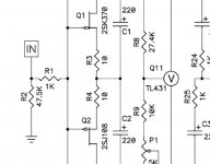
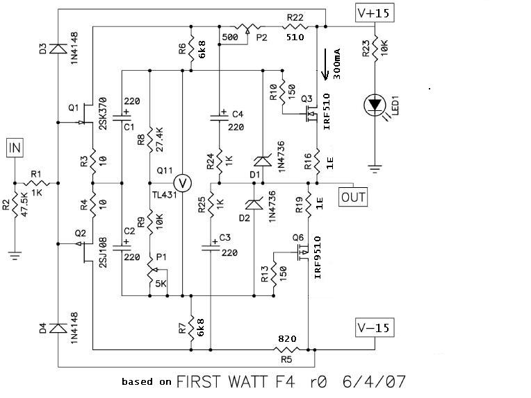
Is there any downside to increasing the value of the F4 input load resistor from 47.5k to something higher like a 100k? This is R2 in the attached schem. 47.5k may be fine, just wanting to know if it's some kind of a tradeoff to increase it, in case I wanted to reduce input load.
In a feble attempt to not look like a complete novice let me add that I think the main reason it's there is to provide a ground reference for the jfet gates when no signal input is attached to the amp. The jfet gate to source/drain impedance is very high, in the megohm range so increasing it to 10% or so of that should still allow it to do a good job. I do wonder though if as you increase it's value you run the risk of decreasing noise immunity. Am I on the right track at all?
thanks
Attachments
Last edited:
Yup you got it! Mine is 200k for example.
Thanks Man
Thanks Man
random question, but have you started? I have a pair of F4 monoblocks and an Impasse preamp here in Austin, perhaps it might be worth bringing them over for you to check out before you start?
Hooked up the 4 Jensen JT-123-ALCF transformes wired as Nelson and Choky pointed out in posts 3399 and 3400 to my F4 headphone board.
I lifted R3 and R4 on the version 2 boards currently in the DIYAudio store on the cap side. I connected both leads to the transformer input (grey/brown)
The output was connected to the F4 board where R3 was lifted and the ground was also connected to the F4 board.
The sound is absolutely superb !!!!Have listened to Etta James, Eva Cassidy, Nina Simone, Phoebe Snow, Judy Collins, Doug McCloud, Laura Nyro and Van Morrison. Voices are amazing as is sound stage. Plenty of detail and outrageous bass. No problem driving the my HiFiMan 500s
Thanks Nelson and Choky for the help. Choky I see why you like the M2 !!!
Might have to build a SE version to drive the Ravens in my system.
Best
Bob[/QUOTE
I
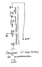
have populated the boards for an SE version as describe above except because the JT 123 ALCF is no longer available I used a pair of JT123 FLPCH transformers recommended for the F6
They are wired 1 to GND
2,3 connected input here from junction of R3,R4
4 connected to 8
6, 7 connected
5 to junction of C1 and C2
I am using 240s and 9240s from the source generg recommended
+/- 18V to the boards
With inputs grounded bias is 225mA using P1 and R9 at 10k
I cannot using P2 lower the DC below .5V
Can someone point me to what I should be looking for?
Using headphone amp schematic from post 3026 (thanks ZM)
THANKS
Bob
input gnded or not , irrelevant for bias and offset
if offset is positive , increase R6
if offset is negative increase R7
nomenclature from #3026 http://www.diyaudio.com/forums/pass-labs/97540-f4-power-amplifier-152.html#post2136465
I didn't check your connection of input xformer
edit:
sch enclosed
if offset is positive , increase R6
if offset is negative increase R7
nomenclature from #3026 http://www.diyaudio.com/forums/pass-labs/97540-f4-power-amplifier-152.html#post2136465
I didn't check your connection of input xformer
edit:
sch enclosed
just ensure that same kind are matched , yes .

Thanks, I know it has been repeated a lot of times in NP's articles but it looks abit different here in F4.
I think my problem is that the JT123 FLPCH transformers have no voltage gain
connect it as autoformer , and it will

ZM
I thought I had this figured out but obviously I don't
using
http://www.jensen-transformers.com/datashts/123flpch.pdf
I wired 1 to GND
2,3 connected input here from junction of R3,R4
4 connected to 8
6, 7 connected
5 to junction of C1 and C2
Now I am thinking
4 to GND
2,3 connected input here from junction of R3,R4
1 connected to 8
6, 7 connected
5 to junction of C1 and C2
Thanks
Bob
Last edited:
 Toaster time!
- Home
- Amplifiers
- Pass Labs
- F4 power amplifier