I've re-drawn the above sketch in the post #17.
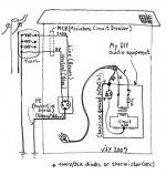
I think that the inserting of the ground loop breaker between the
PE on the chassis and the circuit ground is just a connection --
with respect to both the ground loop breaking and fault circuit
safety.
The important thing is whether the circuit ground is located on
the right position without hum and/or buzz. If there is hum
and/or buzz, the position of the circuit ground might be wrong.
Or, re-layout of the signal ground loop should be considered.
Or, other altenative solution might be introduced as shown in
Zen V4 with the 22ohms attached between the input ground and
the chassis.
Any comment?
Attachments
AndrewT said:your grounding and safety earth look OK.
The thermistor and/or power diode and RF capacitor can all be fitted in parallel rather than exclusively one or other.
I think any voltage diode will do, 50V or 100V will work just as well as 1000V.
AndrewT,
I didn't ask your approval for the already proven standard.
If you don't have any real technical contribution, just sit back
on the highland quietly.
And, don't try to be a big man, just putting your name on the
top of experienced guys. I hope you will kindly undrstand
what I mean!
AndrewT said:Hi,
your grounding and safety earth look OK.
The thermistor and/or power diode and RF capacitor can all be fitted in parallel rather than exclusively one or other.
I think any voltage diode will do, 50V or 100V will work just as well as 1000V.
What's the deal about the RF cap?
Magura
")
Nixie said:Don't just use the diodes; add the resistor and capacitor as described above.
If you want to say, "don't do this or that,"
it should be backed up by reasons.
Otherwise, I see it as an ignorant BS.
Thanks.
Nixie said:AndrewT and myself have already backed it up. Of course, we cannot compensate for your lack of reading comprehension.
Hmm, what could such a circuit be called (I need something to feed google) ?
Cheers
Magura
Nixie said:AndrewT and myself have already backed it up. Of course, we cannot compensate for your lack of reading comprehension.
What about your lack of comprehension about tech?
LOL ~ ^^
 C'mon, guys, keep this to the topic, OK?
While I can arguably see the resistor as part of the safety scheme, I don't see that the cap fits in as a safety item; it's just there to drop RF past the 10 Ohms of resistance and/or the diode drop represented by the bridge. This is a sonic issue, not a safety one.
If you assume that there's going to be sufficient RF voltage present to be physically harmful, you need to get the amp on the bench and determine why it's oscillating rather than simply try to dump the RF to ground.
Face it, the rails on a fairly large amp will run towards 50-75V. Nervous nannies notwithstanding, this is just not an instant-death scenario. I stick my hands in that sort of voltage all the time. 50Vdc you don't even feel. 75Vdc will give you a mild tingling sensation. Above 100Vdc, I turn the thing off before sticking my hands in, as it's enough to be unpleasant.
Derate those figures by half if it's AC you've got your hands in, but that's another question entirely.
If you're really all that concerned with safety--as opposed to sound quality--then wire signal ground straight to chassis ground and be done with it. Ninety jillion pieces of audio equipment have done this over the years and it works okay.
Note that a 10 Ohm 5W resistor will reach its rated wattage when presented with 7.07V. In a worst-case fault scenario, meaning rail voltage is running rampant in your amp, it's toast anyway. It's just along for the ride.
Or you could side step all this fussing and use a varistor to ground...I'm not so sure I'd want to be polluting my ground with rectified RF hash, anyway.
Grey
OK, SY. Your black hairs and long nose looking fresh.
I understand that the small cap could be a RF path to the chassis
from the lifeted circuit common ground point. It could be an
effective means when there is a RF signal at the lifted circuit
ground point. But, I would not force to always have it. It could
be a path to the opposite way.
I understand that the small cap could be a RF path to the chassis
from the lifeted circuit common ground point. It could be an
effective means when there is a RF signal at the lifted circuit
ground point. But, I would not force to always have it. It could
be a path to the opposite way.
GRollins said:...I'm not so sure I'd want to be polluting my ground with rectified RF hash, anyway.
Grey
In some service manuals I have seen the use of 2 AC rail with center tap( signal ground ) to produce just the positive DC rail , through 2 diodes .
Is that what you mean Grey ?
I tried it for a Zen amp and indeed the sound quality was different ;
there was little more hum however , but the test wasnt probably under an optimal layout or enough filtering .
Assume first that you have RF in the audio portion of your circuit--not an outlandish assumption.
--If circuit ground = chassis ground = earth ground, then it goes to ground and all is well
--If you have a resistor between the grounds, then the presumption is that it has "flat" response out to RF and again the RF goes to ground.
--If you have a bridge to ground, then the RF gets rectified, which gets complicated because the rectification process can itself yield RF (you did remember to use a fast/soft bridge, didn't you?). Depending on whether the RF is AM or FM you branch off into other concerns.
There's also that pesky diode drop to deal with if you're trying to get rid of DC.
--A cap between the grounds does nothing whatsoever for DC. Whether it does anything for RF depends on the value and construction of the cap. Too small a value and you miss the lower frequencies you're trying to get rid of. Use something like an electrolytic and it ceases to be a cap at all before it reaches RF.
So you see ESP combining a bridge with a cap and a resistor in an effort to cover the weaknesses of each individually. To my way of thinking, this verges on violating the KISS principle. I'd rather just use a resistor (or varistor) and be done with it.
Grey
I can't believe such a simple circuit is causing so much confusion!
The resistor is to insert higher resistance between the mains earth and signal ground to limit the amplitude of earth loop currents.
The cap is to overcome the inductance of the resistor at higher frequencies, shunting RF to earth rather than letting it rampage inside the equipment, i.e. allowing the system to provide effective RF screening.
The diodes play no part in the earth breaker, they merely provide a safety backup in the event of high current needing to be dumped to earth, as would occur with a catastrophic fault. The resistor and cap would simply pop and let you die.
If you use only a diode to attempt to lift ground it is basically preventing any screening effect of the case and mains earth until a small voltage is present between the two - in which case you have a pretty severe fault/issue elsewhere in the system anyway.
Don't bother. Apparently Babowana has put his fingers in his ears and is going singing "lalalalala I can't hear yoooouu!"Originally posted by richie00boy
If you use only a diode to attempt to lift ground it is basically preventing any screening effect of the case and mains earth until a small voltage is present between the two - in which case you have a pretty severe fault/issue elsewhere in the system anyway.
Granted, I'm not a/the moderator anymore, but can you kinda tone down the attitude?
Sometimes explanations don't work the first time around and a reworded version is required.
Given Babowana's personality and history of posting, I have no reason to believe that insults are called for. I'm sure he isn't trying to cause problems.
Grey
Sometimes explanations don't work the first time around and a reworded version is required.
Given Babowana's personality and history of posting, I have no reason to believe that insults are called for. I'm sure he isn't trying to cause problems.
Grey
Nixie said:Don't bother. Apparently Babowana has put his fingers in his ears and is going singing "lalalalala I can't hear yoooouu!"
I think you need to go and ask milk further,
before your bones are grown up in terrible way.
- Home
- Amplifiers
- Pass Labs
- Diode bridge as loop breaker question