I cheated and used a panasonic FC electrolytic for C5 (10uF) and of course the footprints for C1 and C2 are too small.
I ended up drilling new holes for C2, but there's not enough space for 1uF on C1 as you will see.
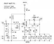
On the copper side, the hole for output seems to be missing, but use the service manual to follow the tracks and you can see the intended placement in the "All" pdf (F2_1)
Be forewarned I have not verified that this actually works, so I take no responsibility for any experiments gone awry
I ended up drilling new holes for C2, but there's not enough space for 1uF on C1 as you will see.
On the copper side, the hole for output seems to be missing, but use the service manual to follow the tracks and you can see the intended placement in the "All" pdf (F2_1)
Be forewarned I have not verified that this actually works, so I take no responsibility for any experiments gone awry
Attachments

Just to make a quick update here: I finally finish my F2.
This is another "used-what-is-available" amplifier. I got a SOZ sitting idle for a while (I switched to use the J-PLH). So what I do is to dismantle this SOZ and try to make every effort to reuse the parts in building the F2.
The following adaptations are made:
1. All MOSFETs are N-channel from SOZ, so the current source in this F2 is a N-channel version. The circuit was published in a former post in this thread by some contributors.
2. The power supply of SOZ is +/-15V, or 30V by re-arranging. This is high for F2 as the design requires 24V. Running at 30V brings too much heat. In the SOZ, there are several 50W 8R big resistors. I put 2*8R in series with the primary of the transformer to bring down the voltage. These resistors run very hot and require heatsink. Also, they are running at LIVE voltage so the heatsink must be grounded properly to ensure safety.
3. There are also several 50W 1R resistors in SOZ, so I use them to build a RCRCRC filter as the main power supply.
4. Essentially the voltage is close but slightly higher than 24V by doing all these. The devices do run hot.
Applying this F2 in my system, which comprises of a B1 buffer and a Fostex FE168 sigma speaker, I do not put the 3*47R in the output. I want to test different settings.
Trying 22R to start with as the damping R (R0 per Nelson's article on current source amp), I find the bass to be rather constrained. Changing it to 36R, the low end opens up drastically. However, there is a feeling that it might be too much (insufficient damping). So I switch to 30R and things are in good shape. The treble seems to be a bit harsh just with this R0. The FE168 sigma, driven by a voltage source, has a very flat high freq response. Under a current drive, it seems that the high end needs some taming. I apply a R1-C1 path (again Nelson's notation in his article) to provide an attenuation shelf. Using what I have in my box, R1 is 36R, and C1 is 4.4uF (2*2.2F in parallel). Characteristics of this network is as attached.
With this network, it sounds smooth and without any fatigue feeling now. More listening to come but I like this F2 a lot.
Attachments
Nelson Pass said:You really do have to screw around with the loading to get the performance.
Having built F2 lite, and then ZV9 without feedback, I had a taste of these. They excite different response from the speaker. It sounds more "alive", like live music, especially voices get stunningly real. But, not loaded and compensated correcty, they can sound nasty.
Tweaking the compensation network can be a real pain and it may take quite some time (and a side comment from the significant other), but in the end it is worth it, because it is possible to get rid of the "shrill" and retain "openness" and "air".
Regards,
Vix


this one lives too!
Thank you Mr Pass
for 5W, it really gets VERY hot! I really did underestimate the dissipation on this one
As you can see from the picture, 24.8V rail voltage and 4.4mV dc offset on this channel.
For the record, nothing explodes if you wire the power in reverse by accident at least not in the first few seconds !
Now ... just need to build some fullrangers to really hear this one sing
Thank you Mr Pass
for 5W, it really gets VERY hot! I really did underestimate the dissipation on this one
As you can see from the picture, 24.8V rail voltage and 4.4mV dc offset on this channel.
For the record, nothing explodes if you wire the power in reverse by accident
at least not in the first few seconds !An externally hosted image should be here but it was not working when we last tested it.
Now ... just need to build some fullrangers to really hear this one sing
Just put the FE127's in Planet10's Classic Fonken GR enclosure, sound pretty decent with LM3875 gainclone.....must try F2. Excuse the noob question. I'd like to give a hack at the Lite version, is it as simple as removing the existing current source and replacing it with a high wattage resistor/light bulbs/calrod heating element for example? Other questions in the attached...
-Thanks
-Thanks
Attachments
Hi everyone,
waking up an old thread to post my first ever message on DIYAudio.
I want to share with you my F2 clone, built last month and still not completely finished mechanically, but already playing sweet music in my student's room.
Here is the unit, with a preamp I also made, and a modest turntable on top (the only digital source at the moment is my pc):
A picture of the two boards:
The power supply section:
The guts of the preamp (also not 100% finished):
And the giant (2.4 meters high) BiB cabinets with FE206E speakers, that my brother and I built (and the bed where I sleep ):
Sorry for the crappy phone pictures, but my camera was not with me when I felt like shooting my latest creations.
It sounds quite impressive, thank you Mr. Pass for sharing your work with the community and thanks to the community for keeping this place so interesting.
Except for the transformer, the channels are completely separate. The big output electrolytics are sitting between the two heatsinks of each channel and are not visible on the pictures.
The filter network for taming the high frequency response of the speakers is using higher resistance than what Mr. Pass suggests for this speaker in his article on current source amplifiers. I would like to try a smaller capacitance too, but still no time to buy a few capacitors of suitable value. I think that the values are very dependent on the enclosure of the speakers. As I'm not at home now, I cannot tell you the exact values I'm using, but could do it over the weekend.
Greetings from Stuttgart,
Filip
waking up an old thread to post my first ever message on DIYAudio
.I want to share with you my F2 clone, built last month and still not completely finished mechanically, but already playing sweet music in my student's room
.Here is the unit, with a preamp I also made, and a modest turntable on top (the only digital source at the moment is my pc):
An externally hosted image should be here but it was not working when we last tested it.
A picture of the two boards:
An externally hosted image should be here but it was not working when we last tested it.
The power supply section:
An externally hosted image should be here but it was not working when we last tested it.
The guts of the preamp (also not 100% finished):
An externally hosted image should be here but it was not working when we last tested it.
And the giant (2.4 meters high) BiB cabinets with FE206E speakers, that my brother and I built (and the bed where I sleep
):An externally hosted image should be here but it was not working when we last tested it.
Sorry for the crappy phone pictures, but my camera was not with me when I felt like shooting my latest creations
.It sounds quite impressive, thank you Mr. Pass for sharing your work with the community and thanks to the community for keeping this place so interesting
.Except for the transformer, the channels are completely separate. The big output electrolytics are sitting between the two heatsinks of each channel and are not visible on the pictures.
The filter network for taming the high frequency response of the speakers is using higher resistance than what Mr. Pass suggests for this speaker in his article on current source amplifiers. I would like to try a smaller capacitance too, but still no time to buy a few capacitors of suitable value. I think that the values are very dependent on the enclosure of the speakers. As I'm not at home now, I cannot tell you the exact values I'm using, but could do it over the weekend.
Greetings from Stuttgart,
Filip
- Home
- Amplifiers
- Pass Labs
- DIY F2 clone