Hi,
Some time ago, I prototyped a modified version of Acaudio's UGS module, and showed it here as I was very pleased with the sound .
.
But I encountered some problems when using it as an Unbalanced to Balanced converter :
the two outputs were of opposite phase, but the peak to peak amplitude was slightly different from one output to the other...
I investigated a bit, and it appeared that this phenomenon was due to the common-mode feedback resistors (R5 & R6 on the linked schematic),
whose value was too low.
So I moved from 4K75 to the hundreds of KOhms (namely 180K) for these resistors, and it cured the problem.
But unfortunately, this modification had a negative impact on the absolute output offset stability,
which began to wander too much for my taste.
This stability is mostly related to the thermal stability of the output mosfets, and their dissipation being quite high,
I began decreasing their bias current (increasing their source resistors).
The offset tamed down, but the sound was worse... Some veil on the highs.
So I searched for a solution allowing both to keep the high bias and to lower the mosfet's dissipation.
It ended up by using a second cascode on the output stage :
A bit more complicated than the first version, but it met my needs.
The offset was down to what I was used to (+/-1mV), as for the sound. It was even better,
with a greater extent to th top of the spectrum, some added speed. I was a lucky man
Then I stumbled upon one of Nelson's crumbs on the UGS, and I immediately wanted to try it
It's based on the use of current mirrors for the "output stage" (the level shifters), instead of mosfets.
Being born to the world of High End using mostly mosfets (thanks Nelson),
it was somewhat conceptually hard for me to move to BJTs, but I made the step,
and here's what I tested :
To go straight to the conclusion, I must confess that (for me) this version is by (a lot of) far superior to the mosfet version, cascode or not.
Ultimate speed, added life to the music, truth everywhere, instrument location, dynamics, widening...
Wowwwww... What a beast !
And from the technical point of view, it's a pleasure. I love the elegant simplicity of the design.
And no more need of common-mode feedback resistors... Provided that the transitors are thermally coupled,
it sticks to 0V, typically 0.1 to 0.2mV, both relative and absolute, without any parts matching.
I've still got some test to perform, e.g. to see if a lower current gain of the mirrors has effect on the sound.
This would allow to dicrease the dissipation, and may be to avoid a thermal coupling.
Just for the pleasure, the whole family
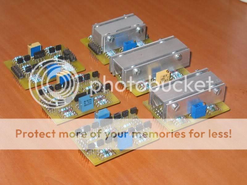
From back to front : The original version, cascoded mosfets, and current mirrors.
And at last, a very warm thank to Nelson for allowing us to have a taste of heaven. Many many thanks
Some time ago, I prototyped a modified version of Acaudio's UGS module, and showed it here as I was very pleased with the sound
.But I encountered some problems when using it as an Unbalanced to Balanced converter :
the two outputs were of opposite phase, but the peak to peak amplitude was slightly different from one output to the other...
I investigated a bit, and it appeared that this phenomenon was due to the common-mode feedback resistors (R5 & R6 on the linked schematic),
whose value was too low.
So I moved from 4K75 to the hundreds of KOhms (namely 180K) for these resistors, and it cured the problem.
But unfortunately, this modification had a negative impact on the absolute output offset stability,
which began to wander too much for my taste.
This stability is mostly related to the thermal stability of the output mosfets, and their dissipation being quite high,
I began decreasing their bias current (increasing their source resistors).
The offset tamed down, but the sound was worse... Some veil on the highs.
So I searched for a solution allowing both to keep the high bias and to lower the mosfet's dissipation.
It ended up by using a second cascode on the output stage :
A bit more complicated than the first version, but it met my needs.
The offset was down to what I was used to (+/-1mV), as for the sound. It was even better,
with a greater extent to th top of the spectrum, some added speed. I was a lucky man
Then I stumbled upon one of Nelson's crumbs on the UGS, and I immediately wanted to try it
It's based on the use of current mirrors for the "output stage" (the level shifters), instead of mosfets.
Being born to the world of High End using mostly mosfets (thanks Nelson),
it was somewhat conceptually hard for me to move to BJTs, but I made the step,
and here's what I tested :
To go straight to the conclusion, I must confess that (for me) this version is by (a lot of) far superior to the mosfet version, cascode or not.
Ultimate speed, added life to the music, truth everywhere, instrument location, dynamics, widening...
Wowwwww... What a beast !
And from the technical point of view, it's a pleasure. I love the elegant simplicity of the design.
And no more need of common-mode feedback resistors... Provided that the transitors are thermally coupled,
it sticks to 0V, typically 0.1 to 0.2mV, both relative and absolute, without any parts matching.
I've still got some test to perform, e.g. to see if a lower current gain of the mirrors has effect on the sound.
This would allow to dicrease the dissipation, and may be to avoid a thermal coupling.
Just for the pleasure, the whole family
From back to front : The original version, cascoded mosfets, and current mirrors.
And at last, a very warm thank to Nelson for allowing us to have a taste of heaven. Many many thanks
Alain Dupont said:Hi,
I followed this adventure on homecinema-fr
great design, wouahhhhh
I am trying to make a pcb of your V3 mirror, a lot of work to do..
Do you have a typon, or anything?
thanks for publishing here
I will replace my 2 CCS-X-Bosoz bords with these !
Regards.
Alain.
Good choice, that's what Cheff did to. Mine replaced first a tube preamp. The most interesting fact in UGS is its capability to be transparent, not limiting. He don't add some stuff or artifficial sound stage. Make attention Cheff pcb design need good eyes and good fingers hability due its stamps size.....Here ie mine :
An externally hosted image should be here but it was not working when we last tested it.
Marc
Alain Dupont said:marc,
These look great!!!
Nice heatsinks too, Great job!
I am not used to make Pcb's and with Osmond_X on my mac it's hard...
I think at first I'll make 2 bords with predrilled Vector circuitbords
Then continue with the pcb...
thanks so much.
Alain.
Cheff will publish all stuff to realize the pcb, according to experiments we done on together it's a quite good support to make some mesurement.
Marc
Hi,
Thanks Alain for kind comments, and sorry Zen-Mod for having ruined your day
As Marc said, I will post soon a pcb, but I'm afraid it will be double-sided. But the circuit is quite simple, and should be easy to route by yourselves. Feel free to draw your version
I just made some measurements last weekend, comparing the three versions, mainly on THD basis. It's only valid as a qualitative reference, and by comparing the curves, since the PC soundcard is not the best device to measure such low levels...
you can find the results here : http://idefixes.phpnet.org/illu/av/preamp_ugs/Mesures/Comparison.htm
where V1 is the first version (posted some time ago),
V2 is the cascode mosfets one, and V3 is the current mirrors version.
Thanks all
Hi Cheff,
I have built a one channel proto but I have not yet powered it up. I have made corrections regarding the polarity of the SuSy connection based on your suggestion at the time. I really like the fact that you only had minimal offset.
I used mosfets only as followers. That was how I increased the output current. I noticed that you included current gain in your mirrors.
I have a couple of questions:
1) What bias current are you using in the JFETs and how do you set it? There is a lot of Idss variation in these parts and other people may have to tweak some values to make your circuit work with BL parts from different batches. The two pots you show seem to adjust only the relative and absolute offset.
2) Did you Vbe match the current mirror transistors? I did, but I don't know how important it is.
3) Why are the emitter resistors on the mirrors so large? It seems that this would limit the output swing. I have always understood that minimal values are best - with a voltage drop of only a few tenths of a volt. Note that I used 100 ohms here. Did you choose your values based on listening tests?
4) The 450/550 transistors on the output have a Vce max of 45V. It seems risky to run them off 24V rails. This is why I used the 696/796 pair.
Once again, I really like your design. I have recently come up with a requirement for a UGS stage and you have inspired me to get back to work on it.
Cheers,
Graeme
Re-Hi, Graeme
IMHO, as the following stage (the amp) has a high impedance, and hence a voltage input, you don't need a high output current. For its major part by far, the current running through the mirrors is shared by the upper and lower mirrors, and the difference of these upper and lower currents is going to ground through the lowest impedance path, i.e. the output resistor Rout, which converts the current to voltage...
The jfet bias current is roughly 3.5 mA/Fet, and it is set by the Fets' source resistors. It obviously depends on the Id=f(Vgs) curve, so Idss matters, but amongst the 6 modules I built, I didn't see huge variations of the bias current, despite of the different batches of BL I had... The important thing here is less the bias current than the transconductance that sets the first stage gain.
Sure, the mirror function is better achieved when Vbe and gain are matched for these BJTs, but honestly, I didn't investigate this issue, and really can't say how it impacts the sound.
Well, I do not have my files handy, but if memory serves, the maximum output swing is around 30V peak to peak, but I'll check and report back. Nevertheless, count it in tens of volts, which is really sufficient for a linestage.
The mirror resistance is here to provide some gain, helping the first stage in order to get a higher open loop gain (around 35dB in simulations). Their values are on par with the drain resistors', with a rough current gain of 2 here. And if the resistor is too low, current will increase, and the dissipation in the output transitors will become too high, so I had to make some compromises between gain and thermal equilibrium. With values here, the current through the output BJTs is around 7mA.
As I stated above, I plan to investigate the effect of a higher emitter resistor (1K to 1K5), both on the sound and on the dissipation, as the output current will decrease. But I'd rather listen to music for the moment
With an output wing of +/-15V (must check), the max Vce will be 34V with a 24V supply, as the emitter resistors drop around 5V. Yes it's close, and it can be an issue if you push it to the limits, but in "normal" use, you don't need that swing. But I'd be interrested in knowing how higher voltage bjts behave compared to the ones I used. Another test...
Thanks, but you were part of my "intellectual" trip to get here
And I really hope you will soon have something working. The end's worth the journey. That's really the best preamp I ever had. May be I made some mistakes/compromises in designing it (please point them out, that's the way I learn), but as is, it's awfully wonderfull Really.
Best,
gl said:Hi Cheff,
I have built a one channel proto but I have not yet powered it up. I have made corrections regarding the polarity of the SuSy connection based on your suggestion at the time. I really like the fact that you only had minimal offset.
I used mosfets only as followers. That was how I increased the output current. I noticed that you included current gain in your mirrors.
IMHO, as the following stage (the amp) has a high impedance, and hence a voltage input, you don't need a high output current. For its major part by far, the current running through the mirrors is shared by the upper and lower mirrors, and the difference of these upper and lower currents is going to ground through the lowest impedance path, i.e. the output resistor Rout, which converts the current to voltage...
1) What bias current are you using in the JFETs and how do you set it? There is a lot of Idss variation in these parts and other people may have to tweak some values to make your circuit work with BL parts from different batches. The two pots you show seem to adjust only the relative and absolute offset.
The jfet bias current is roughly 3.5 mA/Fet, and it is set by the Fets' source resistors. It obviously depends on the Id=f(Vgs) curve, so Idss matters, but amongst the 6 modules I built, I didn't see huge variations of the bias current, despite of the different batches of BL I had... The important thing here is less the bias current than the transconductance that sets the first stage gain.
2) Did you Vbe match the current mirror transistors? I did, but I don't know how important it is.
Sure, the mirror function is better achieved when Vbe and gain are matched for these BJTs, but honestly, I didn't investigate this issue, and really can't say how it impacts the sound.
3) Why are the emitter resistors on the mirrors so large? It seems that this would limit the output swing. I have always understood that minimal values are best - with a voltage drop of only a few tenths of a volt. Note that I used 100 ohms here. Did you choose your values based on listening tests?
Well, I do not have my files handy, but if memory serves, the maximum output swing is around 30V peak to peak, but I'll check and report back. Nevertheless, count it in tens of volts, which is really sufficient for a linestage.
The mirror resistance is here to provide some gain, helping the first stage in order to get a higher open loop gain (around 35dB in simulations). Their values are on par with the drain resistors', with a rough current gain of 2 here. And if the resistor is too low, current will increase, and the dissipation in the output transitors will become too high, so I had to make some compromises between gain and thermal equilibrium. With values here, the current through the output BJTs is around 7mA.
As I stated above, I plan to investigate the effect of a higher emitter resistor (1K to 1K5), both on the sound and on the dissipation, as the output current will decrease. But I'd rather listen to music for the moment
4) The 450/550 transistors on the output have a Vce max of 45V. It seems risky to run them off 24V rails. This is why I used the 696/796 pair.
With an output wing of +/-15V (must check), the max Vce will be 34V with a 24V supply, as the emitter resistors drop around 5V. Yes it's close, and it can be an issue if you push it to the limits, but in "normal" use, you don't need that swing. But I'd be interrested in knowing how higher voltage bjts behave compared to the ones I used. Another test...
Once again, I really like your design. I have recently come up with a requirement for a UGS stage and you have inspired me to get back to work on it.
Cheers,
Graeme
Thanks, but you were part of my "intellectual" trip to get here
And I really hope you will soon have something working. The end's worth the journey. That's really the best preamp I ever had. May be I made some mistakes/compromises in designing it (please point them out, that's the way I learn), but as is, it's awfully wonderfull
Really.Best,
Hi mlloyd1,
Thanks. And for sharing, thank Nelson
There's two main reasons I didn't use folded cascodes.
A psychanalytical one, as I always have been unable to have them properly functionning in any design I built with them, ugs or not... Mea culpa, haven't try hard enough, surely
A more practical one, as I needed a little more open loop gain which I guess I couldn't achieve with a mere folded cascode, or I'm mistaken...
Regards,
cheff:
thanks. i was curious because i am trying to settle on a gain block to use for a "no-overall feedback loop" line stage. at this point, I've pretty much settled on the complementary diffamp jfet feeding complementary folded cascode bipolar transistors. high open loop gain is not a requirement for my needs. looking at the blowtorch discussion, i really wanted to try bipolars instead of mosfets on the back end.
maybe charles hansen will drop a pearl or two.
mlloyd1
CheffDeGaar said:Hi mlloyd1,
Thanks. And for sharing, thank Nelson
There's two main reasons I didn't use folded cascodes.
...
CheffDeGaar said:A more practical one, as I needed a little more open loop gain which I guess I couldn't achieve with a mere folded cascode
There are some practical disadvantages to cascodes and
folded cascodes in particular - they don't add much loop gain,
they are more complex (than nothing), and they cut into the
voltage swing of the circuit relative to the supply.
The advantages are that they provide faster and more linear
operation for the gain devices, and they also allow the use of
better, more refined (read: delicate) devices.
Simulation Headaches
I’m intrigued with this UGS circuit and would like to learn its workings. I usually play with PSPICE (LTSPICE) to work through the operation of a circuit, but I’m having issues with Cheff’s (et al.) circuit. I know folks here have their reservations about usefulness of spice (I’m agreeing), but it has, in the past, helped me build confidence in the design both in its function and my understanding of it, especially when I can finagle the parameters to produce the desired output.
I am having problems with the simulation output. Given an input frequency/amplitude, there is a positive absolute DC offset at the output, irregularity of pos/neg outputs around center, and glitches/spikes. I believe my problem lies in the JFET models and/or my application of them. Have any others simulated this circuit successfully? Any recommendations for taming the offset I’m seeing? Yeah, I know I could just build it, but those JFETs aren’t too cheap or easy to come by. Also, have any tried building this with matched 2sj109/2sj74 JFETs?
Thanks, Willus
Attachments
Willus,
I haven't had problems with spice for this circuit, and I really don't know where your irregular offset comes form...
Here are the JFets models I've used for testing :
.MODEL 2SK389BL NJF (VTO=-420.565M BETA=62.7612M LAMBDA=1M IS=10F RS=8.03465
+ CGD=19.8997P CGS=24P KF=0.00222996F AF=500.504M)
.MODEL 2SJ109BL PJF (VTO=-418.894M BETA=83.8035M LAMBDA=1M IS=10F RS=11.0887
+ CGD=71.6975P CGS=61.6464P PB=1.85382 KF=0.00787907F AF=499.474M)
Sure, the circuit can be built using matched 2SK170 and 2SJ74, but you'll have to match them both in Vgs and transconductance (different Vgs at different drain currents), and make sure their thermal coupling is efficient.
Zetex BJTs are nor mandatory here IMHO, and any low power BJT with gain > 100-200 will do.
Regards
- Home
- Amplifiers
- Pass Labs
- UGS adventures