Errrrr build it ? ")
More seriously, I used an old tv remote for my testings, and finaly kept it as it is small.
I also used my Marantz CD player remote (used the numbers), but the best is to use an universal remote.
I may do that later, something as the Logitech Harmony
Oh, and I have used an application running on my HP iPAQ, this old thing has tactile color screen and IR port.
It's in the setup menu. Rather straight forward.
If you don't see the item in the setup, then you have a firmware problem that counts twice each stepping of the encoder. That would make half menu item not to appear.
I'm sorry, I just set it up once and it was 8 years ago ^^
I'll look at home if I got something useful for you.
If you don't see the item in the setup, then you have a firmware problem that counts twice each stepping of the encoder. That would make half menu item not to appear.
I'm sorry, I just set it up once and it was 8 years ago ^^
I'll look at home if I got something useful for you.
It's in the setup menu. Rather straight forward.
If you don't see the item in the setup, then you have a firmware problem that counts twice each stepping of the encoder. That would make half menu item not to appear.
I'm sorry, I just set it up once and it was 8 years ago ^^
I'll look at home if I got something useful for you.
Ok the volume up/down is working now using the Marantz RC5500SR but other functions are not, will figure out why
. So the procedure is easy like Point and Shoot and Press and Hold
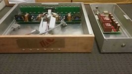
. Thanks MaousseUGS preamp kit
analogair, send an email to Alex_twn on this forum, he speaks english. See my thread: http://www.diyaudio.com/forums/pass-labs/277355-ugs-muse-preamp-gb-10.html
You have to register to the GB:
Connexion
on an online Google sheet, and there is a tab in english as well:
https://docs.google.com/spreadsheet...lhxtWy9w-UnD_kjsFcUI/edit?pli=1#gid=722237733
There is multiple kit offering. You'll need the complete kit to build a preamp, check the google sheet. I think it is kit 1.
Hope it is clearer. SB
After 4 trips to the bank I was finally able to complete the funds transfer to Alex. He should get the funds within the next 48 hours...
Thanks for your help again.
Dennis
Source code .eex .hex files needed?
Hi chaps. In the file source.zip there is no hex or eex file. Don't we need them to program the chip? Also I cannot see different code for the different LCD screens. There were lots of asm files and one other type (can't remember it's name - at work at present) Perhaps I have an incomplete file but there were no errors on unzipping. Can anyone explain this to me please.
Do I need hex eex files?
What files do I need for the different LCD screens?
Many thanks
Happy New year to you all
George
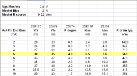
UGS using k170 and j74 with matched curves
If we use k170 and j74 Instead of k389 and j109
and to follow Patrick recomendation for matching curves of k170 and j74 can we use for j74 Rs resistor value 24.3 instead of adding 2.3 degen resistor to original Rs of 22 R
(using j74 with Idss 10.5 and k170 with Idss 9.5)
If we use k170 and j74 Instead of k389 and j109
and to follow Patrick recomendation for matching curves of k170 and j74 can we use for j74 Rs resistor value 24.3 instead of adding 2.3 degen resistor to original Rs of 22 R
(using j74 with Idss 10.5 and k170 with Idss 9.5)
Attachments
Last edited:
I'm not sure I understand.If we use k170 and j74 Instead of k389 and j109
and to follow Patrick recomendation for matching curves of k170 and j74 can we use for j74 Rs resistor value 24.3 instead of adding 2.3 degen resistor to original Rs of 22 R
(using j74 with Idss 10.5 and k170 with Idss 9.5)
I thought that the Euvl design and measurement showed that better matching of the N & P channel curves was achieved by adding an Rdegen to ONLY the P channel device.
i.e. the Nchannel is selected for a particular Idss and then the matching P channel had the higher Idss and this needed the degeneration resistor added to the Source lead of the J74.
Using the yellow highlighted line:
Select an sk170 with an Idss near 6.5mA. This is used without any degeneration resistor.
Select an sj74 with an Idss near 7.6mA This needs a 4r8 degeneration resistor on it's source leg.
When this combination is operated @ 5mA of Id, then both devices have an effective gm=30mS
Last edited:
the Euvl tests & measurements applied when there was no Rs on the N channel device.
He published his report showing how adding an Rs to the Pchannel device corrected for the excess gm.
You are looking at a different situation where the Nchannel has some degeneration, actually more rather than less, so I can't understand how you arrive at adding 2r3.
I don't follow how you came to your proposal.
from Euvl table I took Information about jfets Yfs, Idss, R degen
I am not Interested at all about yellow line which Is someone else choice, not mine
If I like to use p jfet with 10.5 Idss I can see that I need to use 2.3 R degen to j74 together with k170 with 9,8 Idss
that Is how I Interpret table, am I wrong ?
I am not Interested at all about yellow line which Is someone else choice, not mine
If I like to use p jfet with 10.5 Idss I can see that I need to use 2.3 R degen to j74 together with k170 with 9,8 Idss
that Is how I Interpret table, am I wrong ?
I think you are wrong.
If you have two jFETs with Pch Idss=10.6mA & Nch Idss=9.8mA, then you are close to line 6 where the Id should be set to 7mA, or very slightly above.
Add a degereration resistor of 2r3 to the Pch ONLY. There is no Nch degeneration and you end up with a gm for both P & N channel of ~35mS
The circuit you are using is different from that. It shows degen on the Nch of 47r and Pch of 22r.
I cannot see how you should apply Euvl's table to that arrangement.
- Home
- Amplifiers
- Pass Labs
- UGS adventures