Can you post and share your pcb layout and updated schematics with the ccs you used. I planning to build another one since i have plenty of power mosfet to use...
Ditto on the schematics and pcb layout. Do you have any boards left? Maybe there's enough interest for a group buy of boards and/or components?

I strongly advice Replacing R1 with a current source for the input diff pair.
Its obvious now when you look at the schematic that the input diff pair cannot control the VAS when the voltage across R1 is less then half the supply voltage, due the resistive load R2 (sized to split the current equally in the diff pair at normal operation)
Simply put when the supply voltage bellow about half the supply voltage Q3 is turned off and R3 and R4 acts as pull up on the Q6 putting what is left in the reservoir caps across the speakers...
I'm sourcing transistors for my boards. Is there a recommended Hfe range to specify when purchasing the 2SA970's? How tightly should I request matching of each pair?
They don't require much in the way of matching.
That doesn't keep people from going for tight matches anyway...

Hi guys,
I was just reading this thread. just to let you know ...... one of my local suppliers here sells an IRFPC40 ............. these are rated 600v, 6.8A and an RDS on of 1.2 ohms with much the same gate capacitance as the IRF240's............. I don't know if they're still in production and available on your sides of the world but they work fine and they're about half the price of the IRF240's ............. a little under rated current wise I know but if you're not planning on pushing 100's of watts of power they work just great!
IRFPC40 - FET N-C TO247 600V 6A8 1E2
this is a great amp! ................... Thank you Nelson
Hi everybody,
I'm building a C12 with the Tazzz pcb, and I'm wondering, is the input impedance really 10K?
I have 2 option a this point, the B1 buffer, and it seems is 1k output impedance or VTC, which lower the output impedance for levels less than 0 bB, ex. half the volume is 1/4 the impedance, with a quite low output impedance dac 2v output. Any of you can give me some advise, confirmation, suggestion? I will appreciate.
Is a 500W transformer could be enough for the C12, I wont be too far with the Bias, I promise.
Citation 12 rebuild
Due to the generosity of a friend I recently was offered two non-functioning Citation 12s (thanks Dutch), and after looking them up and finding Nelson's mosfet mod article I gladly took them. I used Tazzz's schematic for the complementary version, which had more up-to-date parts than Nelson's original, and decided to do one with IRFP240/9240 and the other with laterals (BUZ901/906).
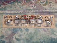
I was unable to obtain boards from Tazzz so I had to fit the circuit on the old board, which was complicated by the fact that the diagrams of the circuit board in Nelson's article aren't very readable and aren't for the complementary version anyway, so I made my own based on the board diagram in the service manual. It's a little busy looking but may be of some use to someone else who wants to try this project.
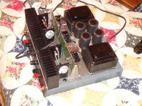
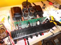
The 240/9240 version went together like a dream and worked perfectly right off. I used Mundorf 10,000uF 4-pole caps in the power supply (I always wanted to try the Jensens but they were too expensive) and 0.10 ohm source resistors, as I couldn't find Tazzz's prescribed 0.01 ohm versions. I didn't do Nelson's prescribed biasing procedure with the oscilloscope but rather just jacked up the bias over time until the heat sinks got up to my target temperature, about 47º, which ended up being around 200mA. Initially the sound was unimpressive (I was coming from an M2) but after a change of preamps and some run-in it sounded really nice. It's not an M2 or F6 - a little aggressive in the upper midrange (strings), but it has better bass (well, more bass anyway) and more grace under pressure than either.
The lateral version was a challenge, and a great learning experience for me, a relative newbie to the secrets of the inner workings of power amps. First lesson - you can't just drop laterals into a circuit designed for vertical mosfets! You get the positive power rail voltage at the output! Yikes! (I did have the pins all connected correctly, buy the way.) After reading and re-reading all the Citation 12 threads here I picked up enough hints to figure out that I needed to change R14 to accommodate the BUZ's lower turn-on voltage. After much experimentation and a few burned gate resistors (the bias circuit tends to oscillate pretty severely at around 100Hz or so if the resistors aren't right) I found that 470 ohms for R14 (Vbe multiplier resistor), 570 ohms for R18, and 680 ohms for R19 work well. Oscillation occurs if the bias is too high and the gate resistor values too low. If R14 is too low you can't get the bias high enough - with 220 ohms I could only get it to 47mA or so. I suppose R14 could be as high as 2K - I was at 470 when I got it to work so I just left it there. These values may or may not work for you but they will at least give you a place to start. I also tried 220pF capacitors from gate to source as Rod Elliott does in his P101 (makes up the difference in capacitance between the NPN and PNP laterals) - don't do it! They made the circuit oscillate like crazy every time I tried them. In the end I settled for around 250mA bias, which gave a heat sink temperature of about 50-52º at idle, and around 54-55º with the cover on after being played for 1-2 hours.
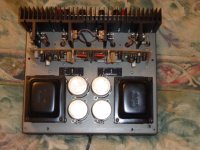
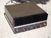
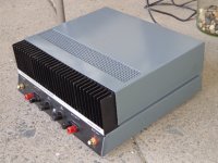
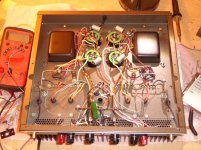
Sound-wise, the lateral version is more even and preferable to the vertical mosfet version. Still not an M2 or F6, but mighty fine. I finished both off by re-doing the case finish - they were both pretty rusty when I got them. Some before/after pics are below, along with the board diagram. The board pics and diagram were too big to show up here so I just linked to them.
Board diagram
Front of board
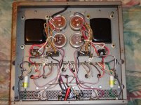
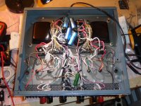
Back of board
Due to the generosity of a friend I recently was offered two non-functioning Citation 12s (thanks Dutch), and after looking them up and finding Nelson's mosfet mod article I gladly took them. I used Tazzz's schematic for the complementary version, which had more up-to-date parts than Nelson's original, and decided to do one with IRFP240/9240 and the other with laterals (BUZ901/906).
I was unable to obtain boards from Tazzz so I had to fit the circuit on the old board, which was complicated by the fact that the diagrams of the circuit board in Nelson's article aren't very readable and aren't for the complementary version anyway, so I made my own based on the board diagram in the service manual. It's a little busy looking but may be of some use to someone else who wants to try this project.
The 240/9240 version went together like a dream and worked perfectly right off. I used Mundorf 10,000uF 4-pole caps in the power supply (I always wanted to try the Jensens but they were too expensive) and 0.10 ohm source resistors, as I couldn't find Tazzz's prescribed 0.01 ohm versions. I didn't do Nelson's prescribed biasing procedure with the oscilloscope but rather just jacked up the bias over time until the heat sinks got up to my target temperature, about 47º, which ended up being around 200mA. Initially the sound was unimpressive (I was coming from an M2) but after a change of preamps and some run-in it sounded really nice. It's not an M2 or F6 - a little aggressive in the upper midrange (strings), but it has better bass (well, more bass anyway) and more grace under pressure than either.
The lateral version was a challenge, and a great learning experience for me, a relative newbie to the secrets of the inner workings of power amps. First lesson - you can't just drop laterals into a circuit designed for vertical mosfets! You get the positive power rail voltage at the output! Yikes! (I did have the pins all connected correctly, buy the way.) After reading and re-reading all the Citation 12 threads here I picked up enough hints to figure out that I needed to change R14 to accommodate the BUZ's lower turn-on voltage. After much experimentation and a few burned gate resistors (the bias circuit tends to oscillate pretty severely at around 100Hz or so if the resistors aren't right) I found that 470 ohms for R14 (Vbe multiplier resistor), 570 ohms for R18, and 680 ohms for R19 work well. Oscillation occurs if the bias is too high and the gate resistor values too low. If R14 is too low you can't get the bias high enough - with 220 ohms I could only get it to 47mA or so. I suppose R14 could be as high as 2K - I was at 470 when I got it to work so I just left it there. These values may or may not work for you but they will at least give you a place to start. I also tried 220pF capacitors from gate to source as Rod Elliott does in his P101 (makes up the difference in capacitance between the NPN and PNP laterals) - don't do it! They made the circuit oscillate like crazy every time I tried them. In the end I settled for around 250mA bias, which gave a heat sink temperature of about 50-52º at idle, and around 54-55º with the cover on after being played for 1-2 hours.
Sound-wise, the lateral version is more even and preferable to the vertical mosfet version. Still not an M2 or F6, but mighty fine. I finished both off by re-doing the case finish - they were both pretty rusty when I got them. Some before/after pics are below, along with the board diagram. The board pics and diagram were too big to show up here so I just linked to them.
Board diagram
Front of board
Back of board
Attachments
-
 DSC02218alt.jpg965.6 KB · Views: 463
 -
 DSC02220alt.jpg924 KB · Views: 439
 -
 DSC02222alt.jpg928.2 KB · Views: 418
 -
 DSC02264alt.jpg874.2 KB · Views: 399
 -
 DSC02265alt.jpg918.8 KB · Views: 188
 -
 DSC02324.JPG161.6 KB · Views: 159
 -
 DSC02315.JPG160.9 KB · Views: 185
 -
 DSC02297alt.jpg898 KB · Views: 177
 -
 DSC02269alt.jpg932.1 KB · Views: 180
 -
 DSC02310.JPG161.9 KB · Views: 191
Last edited:
Nice work Schubert, I must say I've never had much luck with those laterals, all the amps I've built used to break into oscillation at certain frequencies. Strangely I found the plastic version of the original Toshiba TO-3's to be more prone to this than their metal counterparts. As for these Hexfets they seem to be rock solid! ........... I thought it'd be fun to use a cheaper run of the mill hexfet like an IRF530 or similar obviously these 530 amps would be of smaller output power. So just sticking these in is no good, they have such low on resistance that they have to have source resistors! ......... so adding a 0.47 ohm resistor to the source of each transistor solves it nicely and makes for quite a nifty little 25-30 watt amp!
I've actually just finished designing PCB's for Nelson's Mosfet Citation with my own requirements in mind:
1. I wanted a separate plug-in driver PCB and a separate output PCB
2. I wanted as little external wiring with as little mounting hardware as possible
3. Fancy aluminium Extrusions are not always readily available here so I wanted to use a standard extrusion
4. After seeing Nelson's Complementary version I decided I needed to make my PCB's user selectable for either the Complementary or Quasi-Complementary version.
5. It also had to have a relatively small footprint.
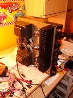
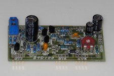
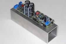
So I managed to build an Amp module with a footprint of 38mm x 160mm with PCB mounted smoothing caps and it all fits neatly on a standard 50mm Aluminium square tube, the beauty about this is you can force cool it! and it just so happens that a stock standard 40mm PC fan press fits nice and snugly into the inside dimensions of the tube. In terms of mounting, 3 bolts hold the PCB to the heatsink. Output configuration is user selectable with a couple of jumpers and component changes.
I've built several prototypes they work well, I'll post some pics. I want to do a production run of 100 PCB's I'm wondering if anyone would be interested in buying any?
I've actually just finished designing PCB's for Nelson's Mosfet Citation with my own requirements in mind:
1. I wanted a separate plug-in driver PCB and a separate output PCB
2. I wanted as little external wiring with as little mounting hardware as possible
3. Fancy aluminium Extrusions are not always readily available here so I wanted to use a standard extrusion
4. After seeing Nelson's Complementary version I decided I needed to make my PCB's user selectable for either the Complementary or Quasi-Complementary version.
5. It also had to have a relatively small footprint.
So I managed to build an Amp module with a footprint of 38mm x 160mm with PCB mounted smoothing caps and it all fits neatly on a standard 50mm Aluminium square tube, the beauty about this is you can force cool it! and it just so happens that a stock standard 40mm PC fan press fits nice and snugly into the inside dimensions of the tube. In terms of mounting, 3 bolts hold the PCB to the heatsink. Output configuration is user selectable with a couple of jumpers and component changes.
I've built several prototypes they work well, I'll post some pics. I want to do a production run of 100 PCB's I'm wondering if anyone would be interested in buying any?
Citation 12 Reworked
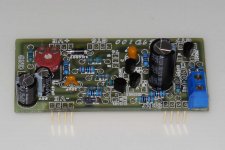
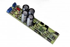
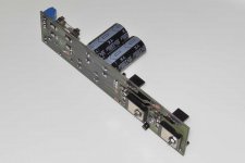
Some Images as promised. Complete Amp with heatsink Length 180mm x Width 50mm. Pic no 4 & 5 show mounting arrangements, 3 M3 bolts hold it all together ( One under the fuse on the right ). output transistors act as the spacers too, these are thermally insulated from the PCB by a couple of small steel washers inserted between the PCB and the transistor. Note the bias transistor on the output PCB for thermal coupling. This fits into a 5mm hole in the heatsink.
Some Images as promised. Complete Amp with heatsink Length 180mm x Width 50mm. Pic no 4 & 5 show mounting arrangements, 3 M3 bolts hold it all together ( One under the fuse on the right ). output transistors act as the spacers too, these are thermally insulated from the PCB by a couple of small steel washers inserted between the PCB and the transistor. Note the bias transistor on the output PCB for thermal coupling. This fits into a 5mm hole in the heatsink.
Attachments
Last edited:
I've actually just finished designing PCB's for Nelson's Mosfet Citation with my own requirements in mind:
1. I wanted a separate plug-in driver PCB and a separate output PCB
2. I wanted as little external wiring with as little mounting hardware as possible
3. Fancy aluminium Extrusions are not always readily available here so I wanted to use a standard extrusion
4. After seeing Nelson's Complementary version I decided I needed to make my PCB's user selectable for either the Complementary or Quasi-Complementary version.
5. It also had to have a relatively small footprint.
So I managed to build an Amp module with a footprint of 38mm x 160mm with PCB mounted smoothing caps and it all fits neatly on a standard 50mm Aluminium square tube, the beauty about this is you can force cool it! and it just so happens that a stock standard 40mm PC fan press fits nice and snugly into the inside dimensions of the tube. In terms of mounting, 3 bolts hold the PCB to the heatsink. Output configuration is user selectable with a couple of jumpers and component changes.
I've built several prototypes they work well, I'll post some pics. I want to do a production run of 100 PCB's I'm wondering if anyone would be interested in buying any?
I'd be interested
Thanks Schubert, just found the facebook page too! .............
Junm boards are $6 for a single channel set
so if you're making stereo amps, $12 gets you 2 driver PCB's and 2 Output PCB's ......... PCB's will be FR4 1.6uM solder masked and component side silk screened for easy component placement. I decided on single sided PCB's since this makes it easier to repair and make any changes or modifications
Prices exclude shipping, I'm forced to use a courier service since our postal system here is unreliable at best
- Status
- This old topic is closed. If you want to reopen this topic, contact a moderator using the "Report Post" button.
- Home
- Amplifiers
- Pass Labs
- citation 12 mos fet